
Want to understand what’s going on under the hood of your car without relying on expensive professional tools? Building your own OBDII scanner is a fantastic project for car enthusiasts and DIYers. This guide will walk you through the process of creating a simple yet effective OBDII scanner harness, allowing you to access your vehicle’s diagnostic data.
Disclaimer: Before we begin, it’s crucial to understand that this is a DIY project. While this guide is based on successful builds, you are undertaking this project at your own risk. Incorrect wiring or handling could potentially damage your vehicle’s electronics. We are not responsible for any issues that may arise from following these instructions. Proceed with caution and double-check your connections at each step.
Tools and Parts You’ll Need
To get started, gather these tools and parts. Having everything ready before you begin will make the process smoother and more efficient.
Tools:
- Wire strippers/cutters: Essential for preparing the wires.
- Needle-nose pliers: Helpful for manipulating small components and crimping.
- Molex crimping tool (Recommended): While not strictly required, a crimping tool will provide a more secure and professional connection for the pins.
- Soldering iron (Recommended): Soldering provides a robust and reliable electrical connection, especially beneficial for the small gauge wires used in this project.
Parts:
- 4-pin Connector: This connector will interface with your OBDII cable. Ensure it’s compatible with the wire size you’ll be using. (4-pin connector example)
- OBD-II Cable: This cable has the standard OBDII connector that plugs into your car. (OBD-II Cable example)
For cost-saving, if you have spare wires available, you can purchase just the female OBD-II connector and wire the necessary connections directly to the 4-pin connector. Make sure you know your wire gauge to select the correct 4-pin connector.
Understanding the OBDII Connector Wiring
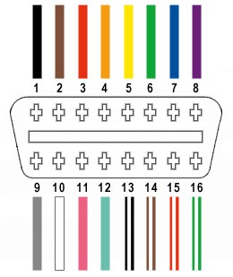
The OBDII connector (OBD2C) has 16 pins, but for this basic scanner, we only need to utilize four key connections:
- Pin 4 (Chassis Ground): Provides the ground connection, typically an orange wire on the OBD2C.
- Pin 6 (CAN [J-2234] High): Carries the CAN bus high signal, usually a green wire on the OBD2C.
- Pin 14 (CAN [J-2234] Low): Carries the CAN bus low signal, often a brown wire with a white stripe on the OBD2C.
- Pin 16 (Battery Power): Provides power, typically a green wire with a white stripe on the OBD2C.
Step-by-Step Guide to Building Your OBDII Scanner Harness
Let’s get hands-on and build your OBDII scanner harness. Follow these steps carefully for a successful build.
Step 1: Preparing the OBD-II Cable Wires
Start by preparing the OBD-II cable. The wires inside are often shielded and sheathed.
- Expose the Wires: Carefully remove the outer sheath and shielding from the OBD2C to access the internal wires.
- Isolate the Required Wires: Separate the four wires we identified earlier (pins 4, 6, 14, and 16) from the rest.
- Organize Unused Wires: Bundle the remaining 12 wires together and secure them with a zip tie to keep them out of the way and prevent accidental shorts.
Step 2: Preparing the Wires for the 4-Pin Connector
The wires in the OBD-II cable are often a smaller gauge (26AWG) than ideally suited for the pins of the 4-pin connector (designed for 22AWG). We need to adjust for this difference.
- Strip Wire Insulation: The wires come pre-stripped with a small amount of exposed wire. Strip off a bit more insulation, aiming for about 3/8″ of exposed wire.
- Thicken the Wire (Optional but Recommended): To ensure a better fit in the pin connector, fold the exposed wire over itself and twist it. This effectively thickens the wire gauge.
- Slide on Rubber Seals: The 4-pin connector kit should include rubber seals. Slide one seal onto each of the four wires. These seals provide environmental protection for the connection.
Step 3: Attaching Wires to the 4-Pin Connector Pins
Now we’ll connect the prepared wires to the pins of the 4-pin connector.
- Insert Wire into Pin: Each pin has two sets of prongs. Insert the exposed wire into the front set of prongs. Ensure the wire is positioned correctly for crimping or soldering.
- Secure Wire (Soldering or Crimping): At this stage, you can choose to either solder or crimp the wire to the pin. Soldering is recommended for a more secure connection, especially with the smaller gauge wire.
Step 4: Soldering the Wires to the Pins (Recommended)
If you’re soldering, follow these steps.
- Solder Connection: Carefully solder the wire to the pin connector. Ensure the solder creates a solid electrical and mechanical connection. If you’re new to soldering, resources like this YouTube video on soldering tips can be helpful.
Step 5: Crimping the Wires to the Pins (Alternative)
If you are using a crimping tool, this is the step for you. If not, you can carefully crimp using needle-nose pliers as described below.
- Crimp with Molex Tool (Ideal): If you have a Molex crimping tool, use it to crimp the front prongs of the pin connector securely around the wire.
- Crimp with Needle-Nose Pliers (Alternative): If you don’t have a crimping tool, use needle-nose pliers. Carefully fold one prong over the wire, then the other, squeezing at an angle to gradually close the prongs around the wire. Videos like this crimping tutorial can provide visual guidance.
- Extra Security (Optional): For added security, you can use pliers to further flatten the crimped prongs, although this may be overkill.
Step 6: Securing the Rubber Seals
Now, secure the rubber seals to provide strain relief and environmental protection.
- Position the Seal: Slide the rubber seal up the wire until it sits between the rear set of prongs on the pin connector.
- Crimp Rear Prongs: Use the same crimping technique (either with a crimping tool or needle-nose pliers) to fold the rear prongs over the rubber seal, securing it in place.
Step 7: Wire Pairing and Twisting (Recommended)
While not definitively proven to be necessary, many DIY guides recommend twisting wire pairs to potentially reduce electromagnetic interference.
- Pair the Wires: Pair the wires as follows:
- Pin 4 (orange) / Pin 16 (green w/white stripe)
- Pin 6 (green) / Pin 14 (brown w/white stripe)
- Twist the Pairs: Twist each pair of wires together.
Step 8: Inserting Pins into the 4-Pin Connector Housing
Finally, assemble the pins into the 4-pin connector housing in the correct orientation.
- Pin Orientation: Refer to the diagram below and insert the pins into the 4-pin connector housing in the following slots:
- Pin 14 (brown w/white stripe) > Connector Slot A
- Pin 6 (green) > Connector Slot B
- Pin 16 (green w/white stripe) > Connector Slot C
- Pin 4 (orange) > Connector Slot D
- Insert and Lock Pins: Push each pin into the correct slot from the rear of the connector until you hear a click. This click indicates the pin is locked securely in place. Needle-nose pliers can be helpful to gently pull the wire from the front to ensure the pin is fully seated and locked.
Your DIY OBDII Scanner Harness is Complete!
Congratulations! You’ve successfully built your own OBDII scanner harness.
Testing Your DIY OBDII Scanner
Now it’s time to test your creation.
- Connect to Vehicle: Plug the OBDII connector end into your vehicle’s OBDII port (usually located under the dashboard). Connect the 4-pin connector end to your chosen OBDII scanning tool or interface.
- Run Diagnostics: Use your scanning tool to perform a diagnostic scan.
This DIY OBDII scanner harness can be used with various OBDII software and devices to read diagnostic trouble codes, clear codes, and access live vehicle data.
If any step was unclear, or you need further clarification, feel free to ask for more details or photos. Happy diagnosing!