
The OBDII (On-Board Diagnostics, Second Generation) protocol is a standardized system that allows external devices to access diagnostic and real-time data from a vehicle’s electronic control units (ECUs). This article provides a deep dive into the Obdii Protocol, covering its history, standards, communication with CAN bus, data logging techniques, and future trends.
A Brief History of OBDII
The need for emissions control in California led to the initial development of OBD systems. In 1991, the California Air Resources Board (CARB) mandated OBD systems in all new vehicles sold in the state. Subsequently, the Society of Automotive Engineers (SAE) recommended the OBDII standard, standardizing diagnostic trouble codes (DTCs) and the connector across manufacturers (SAE J1962).
OBDII adoption expanded globally:
- 1996: Mandatory in the USA for cars and light trucks.
- 2001: Required in the EU for gasoline cars.
- 2003: Extended to diesel cars in the EU (EOBD).
- 2008: US mandated ISO 15765-4 (CAN) as the underlying communication protocol for OBDII.
OBDII and the CAN Bus (ISO 15765-4)
The ISO 15765-4 standard specifies how OBDII utilizes the CAN bus for communication. Key aspects include:
- Bit-rates: 250K or 500K. 500K is most common in modern vehicles.
- CAN Identifiers: 11-bit or 29-bit. 11-bit is prevalent in passenger cars. Functional addressing (0x7DF for 11-bit, 0x18DB33F1 for 29-bit) allows polling all ECUs. Physical addressing targets specific ECUs (0x7E0-0x7E7 for requests, 0x7E8-0x7EF for responses).
- Data Length: 8 bytes per CAN frame.
- ISO-TP (ISO 15765-2): Handles messages exceeding 8 bytes using segmentation and flow control. Single Frame (SF) messages fit within one frame.
Decoding OBDII Data: Modes and PIDs
OBDII data is structured using modes and Parameter IDs (PIDs):
- Modes (Services): Define the type of diagnostic request (e.g., Mode 0x01 for current data, Mode 0x03 for DTCs).
- PIDs: Specify the specific parameter being requested within a mode (e.g., vehicle speed, engine RPM). Mode 0x01 PID 0x00 is mandatory for emissions-related ECUs and indicates supported PIDs.
OBDII Data Logging and Decoding
Data loggers, such as the CANedge, can record raw OBDII data. Key steps for logging and decoding include:
- Determine Bit-rate and Supported PIDs: Send test requests to identify the vehicle’s configuration.
- Configure OBDII Requests: Define the desired PIDs and request frequency.
- Decode Raw Data: Use a DBC (Database Container) file containing decoding rules to convert raw data into physical values (e.g., km/h, °C). Extended multiplexing is often required due to multiple PIDs sharing the same CAN ID.
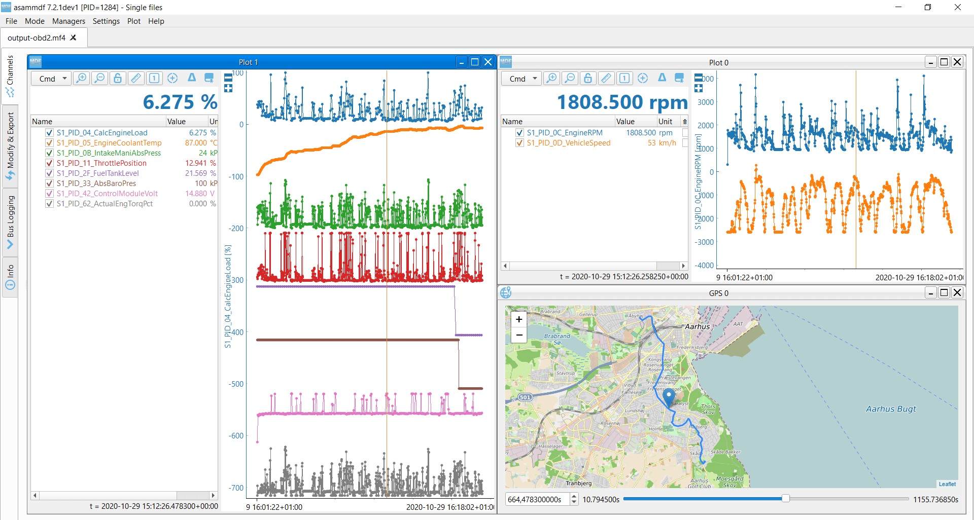 OBD2 data decoded visual plot asammdf CAN bus DBC file
The Future of OBDII
While OBDII remains essential, the automotive landscape is evolving:
- Electric Vehicles: Often use proprietary protocols (e.g., UDS) instead of standard OBDII.
- WWH-OBD and OBDonUDS: Emerging standards aiming to improve data richness and leverage UDS.
- OBDIII: A potential future iteration incorporating telematics for remote diagnostics and emissions testing.
- Data Control: Concerns over data ownership and access may lead to restrictions on third-party OBDII usage.
Conclusion
The OBDII protocol provides a crucial interface for vehicle diagnostics and data analysis. Understanding its intricacies, from the underlying CAN communication to the decoding of modes and PIDs, is essential for anyone working with vehicle data. As the automotive industry continues to advance, the OBDII protocol and its successors will play a critical role in shaping the future of vehicle diagnostics and data utilization.