Understanding the Obdii Plug Pinout is crucial for anyone working with vehicle diagnostics. This guide provides a detailed overview of the OBDII connector, its pin assignments, and how it relates to CAN bus communication. We’ll cover the different OBDII standards, protocols, and practical examples of logging and decoding OBDII data.
What is the OBDII Connector?
The OBDII (On-Board Diagnostics, Second Generation) connector is a standardized 16-pin interface that provides access to a vehicle’s diagnostic trouble codes (DTCs) and real-time data. This data allows mechanics and technicians to diagnose and troubleshoot vehicle issues quickly and efficiently. Located near the steering wheel, the OBDII plug enables communication between a diagnostic tool and the vehicle’s electronic control units (ECUs).
OBDII Plug Pinout and Protocols
While all OBDII connectors share the same 16-pin configuration, the specific function of each pin can vary depending on the vehicle’s communication protocol. Common protocols include:
- CAN Bus (ISO 15765): The most prevalent protocol in modern vehicles, utilizing pins 6 (CAN High) and 14 (CAN Low) for communication.
- ISO 9141-2: Used in some older European and Asian vehicles.
- KWP2000 (ISO 14230-4): Found in certain Asian and European vehicles manufactured before the widespread adoption of CAN bus.
- J1850 VPW/PWM: Primarily used in older GM and Ford vehicles, respectively.
The standard OBDII pinout for a Type A connector is as follows:
| Pin | Function | Protocol(s) |
|---|---|---|
| 1 | Manufacturer Discretionary Use | Varies |
| 2 | J1850 Bus+ | J1850 VPW/PWM |
| 3 | Manufacturer Discretionary Use | Varies |
| 4 | Chassis Ground | All |
| 5 | Signal Ground | All |
| 6 | CAN High (CAN_H) | CAN Bus |
| 7 | K-Line | ISO 9141-2, KWP2000 |
| 8 | Manufacturer Discretionary Use | Varies |
| 9 | Manufacturer Discretionary Use | Varies |
| 10 | J1850 Bus- | J1850 VPW/PWM |
| 11 | Manufacturer Discretionary Use | Varies |
| 12 | Manufacturer Discretionary Use | Varies |
| 13 | Manufacturer Discretionary Use | Varies |
| 14 | CAN Low (CAN_L) | CAN Bus |
| 15 | L-Line | ISO 9141-2, KWP2000 |
| 16 | Battery Power | All |
OBDII and CAN Bus (ISO 15765-4)
ISO 15765-4 defines how OBDII data is transmitted over a CAN bus network. It specifies parameters such as:
- Bit Rates: 250 Kbps or 500 Kbps.
- CAN Identifiers: 11-bit or 29-bit. Common identifiers include 0x7DF (functional addressing) for requests and 0x7E8 (for responses from the Engine Control Module).
- Data Length: 8 bytes per CAN frame.
OBDII Parameter IDs (PIDs)
OBDII Parameter IDs (PIDs) define specific data parameters that can be requested from a vehicle’s ECUs. These PIDs are organized into different modes (services), with Mode $01 providing real-time data such as vehicle speed, engine RPM, and fuel level.
Logging and Decoding OBDII Data
OBDII data loggers can be used to record data for analysis. Decoding this raw data requires knowledge of the PIDs and their scaling information. DBC (Database CAN) files can be used with CAN bus analysis software to decode the raw data into human-readable values.
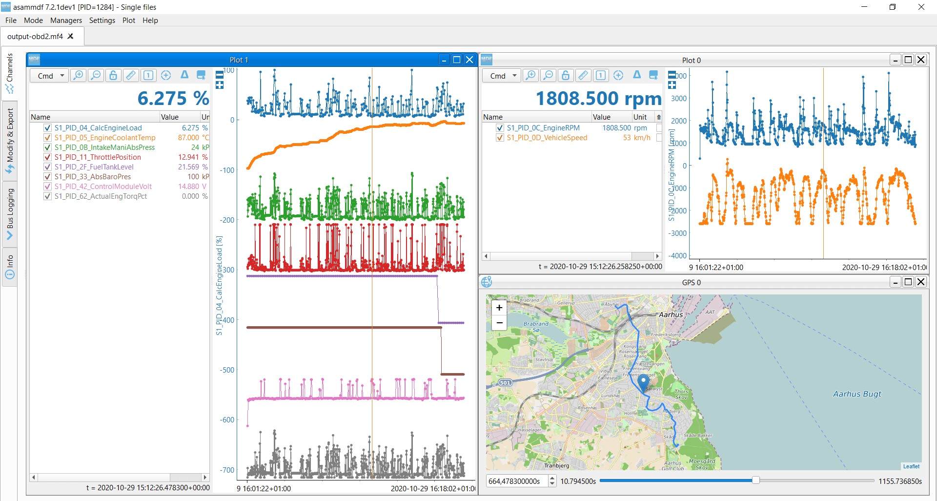 OBD2 data decoded visual plot asammdf CAN bus DBC file
Conclusion
Understanding the OBDII plug pinout and associated protocols is fundamental for vehicle diagnostics. This knowledge empowers you to effectively utilize diagnostic tools, interpret data, and troubleshoot vehicle issues. While this guide focuses on the core aspects of OBDII, continuous learning is encouraged as vehicle technology evolves.