
Want to understand your car’s diagnostics system? This guide provides a practical introduction to the On-Board Diagnostics II (OBDII) protocol, focusing on the crucial Obdii Connector, its pinout, and its role in accessing vehicle data.
Learn about the OBDII connector, its specifications, and how it links to your car’s data network. Discover why understanding the OBDII connector is key to modern vehicle maintenance and diagnostics.
You can also watch introductory videos about vehicle diagnostics online.
Understanding the OBDII System
OBDII is your car’s built-in diagnostic system. It’s a standardized protocol that allows access to diagnostic trouble codes (DTCs) and real-time vehicle data through the OBDII connector.
You’re likely already familiar with OBDII in some way:
Have you ever seen the check engine light illuminate on your dashboard?
That light is an alert from your car’s OBDII system, indicating a potential issue. When you take your car to a mechanic, they use an OBDII scanner to pinpoint the problem.
Mechanics connect an OBDII reader to the 16-pin OBDII connector, usually located near the steering wheel. This tool sends ‘OBDII requests’ to the vehicle, and the car responds with ‘OBDII responses’ containing information like speed, fuel level, or Diagnostic Trouble Codes (DTCs). This communication via the OBDII connector speeds up troubleshooting and repair processes.
Understanding the malfunction indicator light (MIL) as part of the On-Board Diagnostics (OBD) system.
OBDII Compatibility: Is Your Car Equipped?
The short answer is: Most likely, yes!
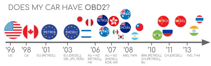
Nearly all newer non-electric vehicles are OBDII compliant, and many utilize the CAN bus communication protocol. For older vehicles, even if a 16-pin connector is present, it might not support OBDII. To confirm OBDII compatibility, consider the vehicle’s origin and year of purchase:
A guide to determine OBDII compliance based on vehicle purchase location and date, covering EU, US, and CAN standards.
A Brief History of OBDII
OBDII originated in California. The California Air Resources Board (CARB) mandated OBD for all new vehicles from 1991 onwards for emissions monitoring.
The Society of Automotive Engineers (SAE) recommended the OBDII standard, which standardized DTCs and the OBD connector across different manufacturers (SAE J1962).
The OBDII standard was gradually implemented:
- 1996: OBDII became mandatory in the USA for cars and light trucks.
- 2001: Required in the EU for gasoline vehicles.
- 2003: Required in the EU for diesel vehicles as well (EOBD).
- 2005: OBDII became mandatory in the US for medium-duty vehicles.
- 2008: US vehicles were required to use ISO 15765-4 (CAN) as the foundation for OBDII communication.
- 2010: OBDII was finally required in US heavy-duty vehicles.
Visual timeline of OBDII history, highlighting its evolution for emission control and data access via CAN bus.
Timeline overview of OBDII history, outlining key milestones in on-board diagnostics development.
Conceptual illustration of OBD3 future trends, including remote diagnostics, emissions testing, cloud connectivity, and IoT integration.
The Future of OBDII Technology
OBDII is expected to remain relevant, but its form is evolving.
Key trends to consider:
Originally designed for emissions control, legislated OBDII is not mandatory for electric vehicles. Consequently, most modern EVs do not support standard OBDII requests, opting instead for OEM-specific UDS communication. This shift often complicates data retrieval from EVs, except in cases where decoding methods have been reverse-engineered, as demonstrated in case studies for electric cars including Tesla, Hyundai/Kia, Nissan, and VW/Skoda EVs.
OBDII faces limitations in data richness and lower-layer protocols. Modern alternatives like WWH-OBD (World Wide Harmonized OBD) and OBDonUDS (OBD on UDS) are emerging. These aim to improve OBD communication by utilizing the UDS protocol. For more on these protocols, refer to introductions to UDS.
In the era of connected cars, traditional OBDII testing methods can be inefficient. Manual emission checks are time-consuming and costly.
The proposed solution is OBD3: integrating telematics into all vehicles.
OBD3 envisions adding a small radio transponder to vehicles, similar to those used for bridge tolls. This would enable vehicles to transmit their Vehicle Identification Number (VIN) and DTCs wirelessly via WiFi to a central server for automated checks.
Many current devices already support transferring CAN or OBDII data via WiFi/cellular, such as the CANedge2 WiFi CAN logger or the CANedge3 3G/4G CAN logger.
While offering convenience and cost savings, OBD3 raises political challenges related to surveillance concerns.
Initially designed for stationary emission controls, OBDII is now widely used by third parties for real-time data acquisition through OBDII dongles, CAN loggers, etc. However, the German automotive industry is considering restricting this access:
OBD was intended for vehicle servicing in repair shops, not for third parties to build data-driven economies by accessing this interface.
– Christoph Grote, SVP Electronics, BMW (2017)
The proposal involves disabling OBDII functionality during driving and centralizing data collection with manufacturers. This would give manufacturers control over automotive big data, argued as a security measure to mitigate car hacking risks, though many view it as a commercially motivated move. The future impact on the market for third-party OBDII services remains uncertain.
Illustration of OBDII future trends, highlighting electric vehicles potentially limiting data access through the OBDII connector.
Enhance Your Vehicle Network Expertise
Interested in mastering CAN bus technology?
Access comprehensive insights with 12 ‘simple intros’ in a detailed 160+ page PDF guide:
Download now
OBDII Standards and Protocols
On-board diagnostics, OBDII, is a higher-layer protocol, functioning like a language for vehicle communication. CAN bus is the communication method, similar to a phone line. OBDII is comparable to other CAN-based higher-layer protocols such as J1939, CANopen, and NMEA 2000.
OBDII standards define the OBDII connector, lower-layer protocols, OBDII parameter IDs (PIDs), and more.
These standards are organized within a 7-layer OSI model, with SAE and ISO standards covering various layers. SAE standards are generally for OBDII defined in the USA, while ISO standards are for the EU. Many standards are technically similar, such as SAE J1979 vs. ISO 15031-5 and SAE J1962 vs. ISO 15031-3.
OSI 7-layer model comparing OBDII and CAN Bus, referencing ISO 15765 and ISO 11898 standards.
Detailed pinout diagram of an OBDII connector socket (female Type A DLC).
The OBDII Connector [SAE J1962]
The 16-pin OBDII connector is your gateway to accessing vehicle data, as specified in SAE J1962 / ISO 15031-3.
The illustration shows a Type A OBDII pin connector, also known as a Data Link Connector (DLC).
Key features of the OBDII connector:
- Typically located near the steering wheel, but its location can vary and may be hidden.
- Pin 16 provides battery power, often even when the ignition is off.
- The OBDII pinout configuration depends on the communication protocol used by the vehicle.
- CAN bus is the most common lower-layer protocol, so pins 6 (CAN-H) and 14 (CAN-L) are frequently connected.
OBDII Connector Types: A vs. B
You might encounter both Type A and Type B OBDII connectors. Type A is standard in cars, while Type B is more common in medium and heavy-duty vehicles.
Both types share similar OBDII pinouts but differ in power supply outputs: 12V for Type A and 24V for Type B. Baud rates can also vary, with cars typically using 500K and heavy-duty vehicles often using 250K (with increasing support for 500K).
Visually, the Type B OBDII connector has an interrupted groove in the middle, distinguishing it from Type A. A Type B OBDII adapter cable is compatible with both Type A and B sockets, whereas a Type A adapter will not fit into a Type B socket.
Comparison of OBDII Connector Type A and Type B, highlighting differences for cars, vans, and trucks according to SAE J1962.
Diagram contrasting OBDII and CAN bus within the ISO 15765 framework.
OBDII and CAN Bus Integration [ISO 15765-4]
Since 2008, CAN bus has been the mandatory lower-layer protocol for OBDII in all US vehicles, as per ISO 15765.
ISO 15765-4 (Diagnostics over CAN or DoCAN) applies specific restrictions to the CAN standard (ISO 11898).
It standardizes the CAN interface for diagnostic equipment, focusing on the physical, data link, and network layers:
- CAN bus bit-rate must be 250K or 500K.
- CAN IDs can be 11-bit or 29-bit.
- Specific CAN IDs are designated for OBD requests and responses.
- Diagnostic CAN frame data length is fixed at 8 bytes.
- The OBDII adapter cable must not exceed 5 meters in length.
OBDII CAN Identifiers (11-bit, 29-bit)
OBDII communication relies on request/response message exchanges.
Most cars use 11-bit CAN IDs for OBDII. The ‘Functional Addressing’ ID is 0x7DF, which queries all OBDII-compatible ECUs for data on a requested parameter (ISO 15765-4). CAN IDs 0x7E0-0x7E7 are for ‘Physical Addressing’ requests to specific ECUs (less common).
ECUs respond with 11-bit IDs in the range 0x7E8-0x7EF. The most frequent response ID is 0x7E8 (ECM, Engine Control Module), followed by 0x7E9 (TCM, Transmission Control Module).
Some vehicles, like vans and medium/heavy-duty vehicles, use extended 29-bit CAN identifiers for OBDII communication.
The ‘Functional Addressing’ CAN ID in this case is 0x18DB33F1.
Responses use CAN IDs from 0x18DAF100 to 0x18DAF1FF (typically 18DAF110 and 18DAF11E). The response ID is sometimes represented as a J1939 PGN, specifically PGN 0xDA00 (55808), which is reserved for ISO 15765-2 in the J1939-71 standard.
Diagram illustrating OBDII protocol request and response frames, showing PID data parameters.
Comparison between OBDII and proprietary CAN bus data in vehicles.
OBDII vs. Proprietary CAN Protocols
Vehicle ECUs operate using proprietary CAN protocols defined by the original equipment manufacturer (OEM), not OBDII. These OEM-specific protocols vary by vehicle brand, model, and year, and are generally inaccessible without reverse engineering.
Connecting a CAN bus data logger to your car’s OBDII connector might capture OEM-specific CAN data, often broadcast at 1000-2000 frames/second. However, newer vehicles often use a ‘gateway’ to block access to this data, allowing only OBDII communication through the OBDII connector.
Think of OBDII as a supplementary higher-layer protocol running alongside the OEM-specific protocol.
Bit-rate and ID Validation
OBDII can use two bit-rates (250K, 500K) and two CAN ID lengths (11-bit, 29-bit), resulting in four possible combinations. Modern cars commonly use 500K and 11-bit IDs. Tools should systematically verify these settings.
ISO 15765-4 outlines an initialization sequence to determine the correct combination. This method relies on the mandatory OBDII response to a specific request and the detection of CAN error frames caused by incorrect bit-rate transmissions.
Newer ISO 15765-4 versions account for OBD communication via OBDonUDS as well as OBDonEDS. This article primarily discusses OBDII/OBDonEDS (OBD on emission diagnostic service as per ISO 15031-5/SAE J1979) versus WWH-OBD/OBDonUDS (OBD on Unified Diagnostic Service as per ISO 14229, ISO 27145-3/SAE J1979-2).
To test for OBDonEDS vs. OBDonUDS, tools can send UDS requests with 11-bit/29-bit functional address IDs for service 0x22 and data identifier (DID) 0xF810 (protocol identification). Vehicles supporting OBDonUDS must have ECUs that respond to this DID.
OBDonEDS (aka OBDII, SAE OBD, EOBD, or ISO OBD) is prevalent in non-EV cars, while WWH-OBD is mainly used in EU trucks/buses.
Flowchart illustrating OBDII bit-rate and CAN ID validation process according to ISO 15765-4.
Overview of the five lower-layer OBDII protocols: CAN (ISO 15765), KWP 2000, SAE J1850, and ISO 9141.
Five Lower-Layer OBDII Protocols
CAN is now the primary lower-layer protocol for OBDII as per ISO 15765.
For older vehicles (pre-2008), other protocols were used. Their pinouts can help identify which protocol is in use:
- ISO 15765 (CAN bus): Mandatory in US cars since 2008, now widely used.
- ISO14230-4 (KWP2000): Keyword Protocol 2000, common in 2003+ Asian cars.
- ISO 9141-2: Used in EU, Chrysler, and Asian cars from 2000-04.
- SAE J1850 (VPW): Mostly in older GM vehicles.
- SAE J1850 (PWM): Mostly in older Ford vehicles.
ISO-TP for OBDII Message Transport [ISO 15765-2]
OBDII data is transmitted over CAN bus using ISO-TP (ISO 15765-2), a transport protocol that allows payloads exceeding 8 bytes. This is essential for OBDII functions like retrieving the Vehicle Identification Number (VIN) or Diagnostic Trouble Codes (DTCs). ISO 15765-2 manages segmentation, flow control, and reassembly.
For shorter OBDII data, ISO 15765-2 uses ‘Single Frame’ (SF) format. The first data byte (PCI field) indicates payload length, leaving 7 bytes for OBDII communication.
Diagram illustrating ISO 15765-2 ISO-TP OBDII frame types.
The OBDII Diagnostic Message [SAE J1979, ISO 15031-5]
An OBDII CAN message consists of an identifier, data length (PCI field), and data, which includes Mode, parameter ID (PID), and data bytes.
Breakdown of an OBDII message structure, explaining raw mode, PID, ID, and data bytes.
OBDII Request/Response Example
Consider a request/response example for ‘Vehicle Speed’.
An external tool sends a request to the car (CAN ID 0x7DF) with 2 payload bytes: Mode 0x01 and PID 0x0D. The car responds (CAN ID 0x7E8) with 3 payload bytes, including the speed value in the 4th byte, 0x32 (50 decimal).
OBDII PID 0x0D decoding rules indicate a physical value of 50 km/h.
Example of an OBDII request (7DF) and response (7E8) sequence for vehicle speed.
Example of OBDII PID 0D for vehicle speed, detailing data interpretation.
Overview of OBDII’s 10 service modes, including current data, freeze frame, and DTC clearing.
The 10 OBDII Services (Modes)
There are 10 standardized OBDII diagnostic services (modes). Mode 0x01 provides real-time data, while others manage diagnostic trouble codes (DTCs) and freeze frame data.
Vehicles may not support all OBDII modes and can include OEM-specific modes beyond these 10.
In OBDII messages, the mode is in the second byte. Requests use the mode directly (e.g., 0x01), while responses add 0x40 to the mode (e.g., 0x41).
OBDII Parameter IDs (PIDs)
Each OBDII mode contains parameter IDs (PIDs).
Mode 0x01, for example, has ~200 standardized PIDs for real-time data like speed, RPM, and fuel level. However, vehicles may only support a subset of these PIDs.
One PID is particularly important:
If an emissions-related ECU supports OBDII services, it must support mode 0x01 PID 0x00. Responding to PID 0x00, the ECU indicates support for PIDs 0x01-0x20. PID 0x00 serves as a basic OBDII compatibility test. PIDs 0x20, 0x40, …, 0xC0 can determine support for other mode 0x01 PIDs.
Repetition of the diagram illustrating OBDII protocol request and response frames, highlighting PID data parameters.
Screenshot of an OBDII PID overview tool, specifically for service 01.
OBDII PID Overview Tool
SAE J1979 and ISO 15031-5 appendices detail scaling information for standard OBDII PIDs, enabling data decoding into physical values.
For mode 0x01 PID lookups, utilize the OBDII PID overview tool. It assists in constructing OBDII request frames and dynamically decoding responses.
OBDII PID overview tool
Logging and Decoding OBDII Data
This section demonstrates logging OBDII data using the CANedge CAN bus data logger.
The CANedge allows custom CAN frame configuration for OBDII logging.
Connect the CANedge to your vehicle via an OBDII-DB9 adapter cable.
Diagram showing OBDII PID data logger request (7df) and response (7e8) process.
Image showing bit-rate validation for OBDII testing.
Screenshot from asammdf software displaying OBDII validation PID test responses.
#1: Bit-rate, ID & Supported PID Testing
ISO 15765-4 provides methods to determine vehicle bit-rate and IDs. Test this with CANedge:
- Send a CAN frame at 500K; if successful, proceed; else, try 250K.
- Use the identified bit-rate for communication.
- Send ‘Supported PIDs’ requests and analyze results.
- Determine 11-bit or 29-bit IDs based on response IDs.
- Identify supported PIDs from response data.
Plug & play configurations are available for these tests.
Most 2008+ non-EV cars support 40-80 PIDs using 500K bit-rate, 11-bit CAN IDs, and OBDII/OBDonEDS protocol.
Multiple responses to a single OBD request (using 0x7DF) are common, as it polls all ECUs. All OBDII/OBDonEDS-compliant ECUs must support service 0x01 PID 0x00, leading to numerous responses. Fewer ECUs respond to subsequent ‘Supported PIDs’ requests. The ECM ECU (0x7E8) often supports all PIDs, reducing busload by directing requests only to this ECU using ‘Physical Addressing’ CAN ID 0x7E0.
#2: Configuring OBDII PID Requests
Once you know your vehicle’s supported OBDII PIDs, bit-rate, and CAN IDs, configure your transmit list with desired PIDs.
Consider:
- CAN IDs: Use ‘Physical Addressing’ request IDs (e.g., 0x7E0) to avoid multiple responses.
- Spacing: Add 300-500 ms between OBDII requests to prevent ECU overload.
- Battery Drain: Use triggers to stop transmissions when the vehicle is inactive.
- Filters: Filter for OBDII responses if OEM-specific CAN data is also present.
The device is now set to log raw OBDII data.
Example of a CANedge OBDII PID request transmit list.
Visual plot of decoded OBDII data in asammdf, utilizing a CAN bus DBC file.
#3: DBC Decoding of Raw OBDII Data
To analyze and visualize logged data, decode raw OBDII data into physical values.
Decoding information is in ISO 15031-5/SAE J1979 and online resources like Wikipedia. A free OBDII DBC file is available to simplify DBC decoding in CAN bus software tools.
OBDII data decoding is more complex than standard CAN signals because different OBDII PIDs use the same CAN ID (e.g., 0x7E8). The CAN ID alone isn’t enough to identify payload signals.
Signal identification requires CAN ID, OBDII mode, and OBDII PID. This ‘extended multiplexing’ is supported by DBC files.
CANedge: OBDII Data Logger
The CANedge enables easy OBDII data recording to an 8-32 GB SD card. Connect to a vehicle to start logging and decode data using free software/APIs and the OBDII DBC file.
OBDII logger intro
CANedge
OBDII Multi-Frame Examples [ISO-TP]
OBDII uses ISO-TP (ISO 15765-2) for all data communication. Most examples so far have been single-frame. This section covers multi-frame communication.
Multi-frame OBDII requires flow control frames. A static flow control frame can be transmitted ~50 ms after the initial request frame.
CAN software/API tools supporting ISO-TP, like CANedge MF4 decoders, are needed for multi-frame OBDII responses.
Example of an OBDII multi-frame request message for vehicle identification number.
Example 1: OBDII Vehicle Identification Number (VIN)
The Vehicle Identification Number (VIN) is crucial for telematics and diagnostics. Retrieve it using OBDII mode 0x09 and PID 0x02:
The tester tool sends a Single Frame request with PCI field (0x02), service identifier (0x09), and PID (0x02).
The vehicle responds with a First Frame containing PCI, length (0x014 = 20 bytes), mode (0x49), and PID (0x02). Byte 0x01 follows the PID, indicating one Number Of Data Items (NODI). The remaining 17 bytes form the VIN, convertible from HEX to ASCII.
Example 2: OBDII Multi-PID Request (6x)
External tools can request up to 6 mode 0x01 OBDII PIDs in one request frame. The ECU responds with data for supported PIDs (skipping unsupported ones), possibly across multiple frames via ISO-TP.
This method enhances data collection efficiency but complicates signal encoding, making generic OBDII DBC files less effective. It’s generally not recommended.
The multi-frame response is similar to the VIN example but includes requested PIDs and their data. PIDs are often ordered as requested.
Decoding this response via DBC files is complex and not recommended for practical data logging unless specialized tools are used. It involves extended multiplexing, making DBC generalization difficult. Custom scripts and recording transmit messages could help, but are complex to scale.
Example 3: OBDII Diagnostic Trouble Codes (DTCs)
Use OBDII mode 0x03 (‘Show stored Diagnostic Trouble Codes’) to request emissions-related DTCs. No PID is needed in the request. ECUs respond with the number of stored DTCs (possibly zero), with each DTC using 2 data bytes, requiring multi-frame responses for more than 2 DTCs.
The 2-byte DTC value is split into category (first 2 bits) and a 4-digit code (14 bits in hexadecimal). Decoded DTC values can be found using OBDII DTC lookup tools.
Example: a request to an ECU with 6 stored DTCs.
Example of OBDII DTC decoding and DBC interpretation.
OBDII Data Logging Use Cases
OBDII data from cars and light trucks has diverse applications:
Car Data Logging
OBDII data can reduce fuel costs, improve driving habits, test parts, and aid insurance assessments.
OBDII logger
Real-Time Car Diagnostics
OBDII interfaces stream human-readable data for real-time vehicle diagnostics.
OBDII streaming
Predictive Maintenance
IoT OBDII loggers monitor vehicles to predict and prevent breakdowns.
Predictive maintenance
Vehicle Black Box Logger
OBDII loggers act as vehicle ‘black boxes’ for dispute resolution and diagnostics.
CAN bus blackbox
Have an OBDII data logging application? Contact us for expert consultation.
Contact us
Explore more guides in our tutorials section or download the ‘Ultimate Guide’ PDF.
Need to log/stream OBDII data?
Get your OBDII data logger today!
Buy now
Contact us
Recommended for You
OBDII DATA LOGGER: EASILY LOG & CONVERT OBDII DATA
CANEDGE2 – PRO CAN IoT LOGGER
CAN BUS INTERFACE: STREAMING OBDII DATA WITH SAVVYCAN