Understanding the OBDII (On-Board Diagnostics, Second Generation) connector and its relationship to the CAN (Controller Area Network) bus is crucial for vehicle diagnostics and data logging. This guide provides a detailed overview of the Obdii Canbus Pinout, including connector types, communication protocols, and practical applications.
OBDII Connector and Pinout: Type A vs. Type B
The OBDII connector, often located near the steering wheel, provides access to vehicle data through a standardized 16-pin interface. Two main types exist:
- Type A: Primarily used in passenger cars, featuring a 12V power supply.
- Type B: Common in heavy-duty vehicles, utilizing a 24V power supply and distinguishable by a notch in the connector.
While pin assignments for power, ground, and chassis ground are consistent across both types, pins dedicated to communication protocols can vary. Crucially for CANbus communication:
- Pin 6: CAN High (CAN-H)
- Pin 14: CAN Low (CAN-L)
These pins carry the differential signals that constitute CANbus communication.
OBDII and CANbus: ISO 15765-4
Since 2008, ISO 15765-4 (also known as Diagnostics over CAN or DoCAN) has mandated CANbus as the primary communication protocol for OBDII in US vehicles. This standard defines specific parameters for OBDII over CAN:
- Bitrate: 250 Kbps or 500 Kbps
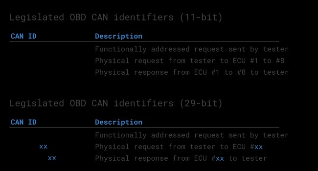
- CAN Identifiers: 11-bit or 29-bit
- 11-bit: Functional Addressing (0x7DF) for general requests, Physical Addressing (0x7E0-0x7E7) for specific ECUs. Responses use 0x7E8-0x7EF.
- 29-bit: Functional Addressing (0x18DB33F1) for general requests, responses use 0x18DAF100 to 0x18DAF1FF.
- Frame Length: 8 bytes
 OBD CAN bus Identifiers
OBDII Diagnostic Messages and Parameter IDs (PIDs)
OBDII diagnostic messages consist of Modes and Parameter IDs (PIDs):
- Modes: Define the type of diagnostic request (e.g., Mode 0x01 for current data).
- PIDs: Specify the specific parameter being requested (e.g., vehicle speed, engine RPM).
Each Mode contains a set of supported PIDs. Mode 0x01, focusing on real-time data, includes a wide range of PIDs defined in SAE J1979 and ISO 15031-5. PID 0x00 within Mode 0x01 is mandatory for all compliant ECUs and indicates supported PIDs.
ISO-TP and Multi-Frame Communication
For data exceeding the 8-byte CAN frame limit (e.g., VIN or DTCs), ISO-TP (ISO 15765-2) enables segmentation of larger messages into multiple frames. This involves flow control mechanisms to ensure reliable transmission and reassembly of the complete message.
Conclusion
Understanding the OBDII CANbus pinout and associated protocols is fundamental for anyone working with vehicle diagnostics, data logging, or fleet management. This knowledge allows for effective communication with vehicle ECUs, retrieval of diagnostic information, and analysis of vehicle performance data. Utilizing tools capable of CANbus communication and decoding, alongside resources like OBDII DBC files, further enhances the ability to extract valuable insights from vehicle data.