
For automotive enthusiasts and DIY mechanics, having the right tools for vehicle diagnostics is essential. While professional scan tools offer extensive capabilities, sometimes a simple custom cable can bridge the gap for specific diagnostic needs. This guide will walk you through the process of creating your own 4-pin to OBDII cable, enabling you to connect to your vehicle’s diagnostic system for basic troubleshooting and error code checks.
Disclaimer: This guide is for informational purposes only and based on personal experience. Automotive electrical work should be performed with caution. The author is not responsible for any damage to your vehicle or equipment resulting from following these instructions. Proceed at your own risk.
Tools and Parts You Will Need
Before you begin, gather the necessary tools and parts. Having everything prepared beforehand will streamline the cable assembly process.
Tools:
- Wire strippers/cutters
- Needle-nose pliers
- Soldering iron and solder (recommended for a robust connection)
- Molex crimping tool (optional, but recommended for professional crimping)
Parts:
- 4-Pin Connector (Link to example part – ensure pin/wire size compatibility: 22-16AWG, insulation/seal size: 1.3-1.7mm)
- OBD-II Cable (Link to example part)
Alternative Parts (Cost-Saving Option):
If you have spare automotive wire available, you can reduce costs by purchasing only a female OBD-II connector and using your own wire to create the necessary connections to the 4-pin connector. Ensure your wire gauge is compatible with the chosen 4-pin connector.
Understanding the Wiring
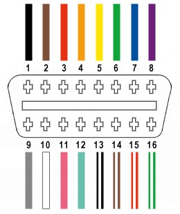
The OBD-II connector (OBD2C) has 16 pins, but for this 4-pin to OBDII cable, we will only utilize four essential connections:
- Pin 4: Chassis Ground (typically an orange wire on the linked OBD2C)
- Pin 6: CAN High (CAN [J-2234] High; typically a green wire on the linked OBD2C)
- Pin 14: CAN Low (CAN [J-2234] Low; typically a brown wire with a white stripe on the linked OBD2C)
- Pin 16: Battery Power (typically a green wire with a white stripe on the linked OBD2C)
These pins are crucial for basic CAN (Controller Area Network) communication, which is commonly used in modern vehicle diagnostics.
Step-by-Step Guide to Building Your Cable
Let’s proceed with the step-by-step instructions to assemble your custom 4-pin to OBDII cable.
Step 1: Prepare the OBD-II Cable Wires
Begin by preparing the OBD-II cable. If you are using a full OBD-II cable, carefully remove the outer sheath and shielding to access the individual wires. Identify and separate the four wires you will be using: Pin 4 (Ground), Pin 6 (CAN High), Pin 14 (CAN Low), and Pin 16 (Battery Power). Bundle the remaining wires and secure them out of the way using a zip tie or electrical tape to keep your workspace tidy.
Step 2: Prepare the Wire Ends for the 4-Pin Connector
The wires in the linked OBD-II cable are often 26AWG, which is slightly smaller than the 22AWG pin size of the example 4-pin connector. To ensure a secure connection, you’ll need to “thicken” the wire ends. Carefully strip approximately 3/8″ of insulation from the end of each of the four selected wires. Fold the exposed wire strands over onto themselves and twist them tightly to increase the wire gauge and improve contact within the pin. Slide a rubber seal (provided with the 4-pin connector kit) onto each wire.
Step 3: Attach Wires to 4-Pin Connector Pins
Take one pin from the 4-pin connector kit. You’ll notice two sets of prongs on the pin. The front prongs are designed to crimp onto the exposed wire, and the rear prongs are for crimping onto the wire seal. Insert the prepared wire end into the front of the pin, ensuring the exposed wire aligns with the front prongs. Use needle-nose pliers to hold the wire in place if needed, as the wire may be thin compared to the pin size.
Step 4: Soldering the Wire to the Pin (Recommended) or Crimping
For a more reliable and robust connection, soldering the wire to the pin is highly recommended. Solder provides a strong mechanical and electrical bond, especially beneficial when working with thinner wires. If you choose to solder, carefully apply solder to the area where the wire meets the front prongs of the pin. Ensure the solder flows smoothly and creates a solid connection.
Step 5: Crimping the Front Prongs (If Not Soldering)
If you prefer crimping or do not have soldering equipment, use a Molex crimping tool for the best results. If a crimping tool is unavailable, needle-nose pliers can be used cautiously. Carefully fold one front prong over the wire using the pliers, and then repeat with the other prong, ensuring a secure crimp. For added security, you can gently squeeze the crimped prongs further with pliers.
Step 6: Crimping the Rear Prongs for the Seal
Slide the rubber seal up the wire until it sits between the rear prongs of the connector pin. Use the same crimping technique as in Step 5 to fold the rear prongs over the rubber seal, securing it in place and providing strain relief for the wire.
Step 7: Wire Pairing and Twisting (Recommended)
Although the exact reason is not definitively known, many DIY guides recommend twisting pairs of wires. It is believed this can help reduce electromagnetic interference and improve signal integrity, especially for CAN bus communication. Pair and twist the wires as follows:
- Pin 4 (orange – Ground) / Pin 16 (green w/white stripe – Battery Power)
- Pin 6 (green – CAN High) / Pin 14 (brown w/white stripe – CAN Low)
Step 8: Insert Pins into the 4-Pin Connector Housing
Refer to the following pinout diagram and insert the completed pins into the 4-pin connector housing (4PC) in the correct orientation:
- Connector Slot A: Pin 14 (brown w/white stripe – CAN Low)
- Connector Slot B: Pin 6 (green – CAN High)
- Connector Slot C: Pin 16 (green w/white stripe – Battery Power)
- Connector Slot D: Pin 4 (orange – Ground)
Insert each pin into the rear of the connector housing until you hear an audible “click,” indicating that the pin is securely locked in place. You can use needle-nose pliers to gently pull on the wire to ensure the pin is locked.
Cable Completion and Testing
Congratulations! Your custom 4-pin to OBDII cable is now assembled.
Before using your cable for critical diagnostics, it is highly recommended to test it. Connect the OBD-II end to your vehicle’s OBD-II port and the 4-pin end to your diagnostic tool or interface. Perform a basic diagnostic check, such as reading and clearing error codes, to verify the cable’s functionality.
If you encounter any issues or have questions, review each step and double-check your wiring. With careful assembly and testing, this DIY 4-pin to OBDII cable can be a valuable tool for your automotive diagnostic needs.