
Using VCDS (Vag-Com Diagnostic System) with Windows 7 Starter can be a valuable tool for diagnosing car problems. When faced with multiple Diagnostic Trouble Codes (DTCs) without a clear cause, a systematic approach to troubleshooting is essential. This article outlines a “divide and conquer” method for diagnosing intermittent electrical faults, specifically focusing on starter relay issues using VCDS on a system running Windows 7 Starter.
Understanding the Challenge of Intermittent DTCs
Intermittent DTCs can be particularly challenging to diagnose. A common approach is to clear the codes and observe if and when they reappear, looking for patterns that might reveal a cause-and-effect relationship. This process often requires patience and careful observation. When a stable DTC pattern emerges, focusing on one of the more obvious faults is a good starting point.
Focusing on Starter Relay Issues
For instance, if the VCDS scan on your Windows 7 Starter system reveals intermittent DTCs related to the Engine Control Unit (ECU), specifically the starter motor circuit, this could be a good place to begin. This circuit is relatively self-contained, making it easier to isolate potential problems.
Let’s say your VCDS scan shows these three DTCs for the ECU:
- 5273 – Output for Starter Relay: P0616 00 [038] – Short to Ground
- 5459 – Control Circuit for Starter Relay 2 :P3048 00 [038] – Short to Ground
- 4710 – No Communications with Airbag Control Module
We might initially set aside the airbag module fault (DTC 4710) if the freeze frame data indicates the engine wasn’t running when the fault occurred. This suggests it might be related to the cranking process.
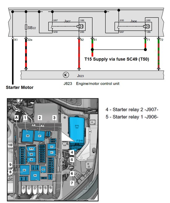 Simplified wiring diagram for an Audi A3 8V starter circuit.
Analyzing the Starter Relay Circuit
To understand the electrical behavior during engine cranking, refer to a simplified wiring diagram (WD). The diagram above illustrates a system with two starter relays (common in vehicles with Start-Stop functionality).
Relays have two key components: the “power” circuit and the “control” circuit. The power circuit handles the high current needed to engage the starter motor. In this example, two relays (J906 and J907) are arranged in a sequence. J906 switches battery voltage to an intermediate point, and J907 then switches this voltage to the starter motor. The control circuit activates these relays. Each relay’s coil is controlled by a separate pin on the ECU (J623), and the control circuit is powered by the car’s T15 voltage rail (often labeled T50 in the cranking circuit).
Pinpointing the Problem
DTC 5459 points to an intermittent short-to-ground in the control circuit of relay 2 (J907). DTC 5273 suggests a similar short on the output side of the relay circuit.
Based on this information, a logical next step is to inspect relay 2 (J907), typically located on the “B” fuse panel in the engine bay. Look for any visible damage to the relay or its housing. Unplug the relay and examine the contacts on both the relay and the fuse panel. Consider swapping relay 1 and relay 2 to see if the DTC descriptions change, which could further isolate the faulty component. Remember, safety is paramount when working with electrical components. Disconnect the battery negative terminal before handling any relays or fuses.
Conclusion
Using VCDS with Windows 7 Starter, coupled with a methodical diagnostic approach, can help pinpoint intermittent electrical faults like those in the starter relay circuit. By carefully analyzing DTCs, understanding the underlying circuitry, and performing targeted inspections, you can effectively troubleshoot and resolve car problems. Remember to consult the vehicle’s specific wiring diagrams and repair manuals for detailed information and safety procedures.