
Optical Bus Diagnostics Vcds is essential for modern vehicle repair. CARDIAGTECH.NET provides cutting-edge solutions for automotive diagnostics. Master optical bus systems, VCDS applications, and troubleshooting strategies for automotive excellence.
1. Understanding Optical Bus Systems in Modern Vehicles
Modern vehicles rely heavily on sophisticated communication networks to ensure seamless operation of various components. Among these networks, the optical bus system, often employing Media Oriented Systems Transport (MOST) protocol, plays a crucial role in transmitting data between multimedia, infotainment, and driver assistance modules. Understanding the intricacies of these systems is paramount for effective diagnostics and repair.
1.1 The Role of Optical Bus Systems
Optical bus systems utilize fiber optic cables to transmit data as light signals, offering several advantages over traditional electrical wiring. These advantages include higher bandwidth, immunity to electromagnetic interference, and lighter weight. The MOST bus, a common implementation of optical bus technology, is specifically designed for multimedia applications in vehicles, enabling high-speed data transfer between components such as the radio, navigation system, amplifier, and display units.
1.2 Key Components of an Optical Bus Network
An optical bus network typically consists of several key components, each playing a vital role in the overall system’s functionality:
- Control Unit: The central processing unit that manages data flow and communication within the network.
- Optical Transceivers: Devices that convert electrical signals into light signals for transmission over fiber optic cables and vice versa.
- Fiber Optic Cables: The physical medium for transmitting data as light signals.
- Modules: Individual components connected to the network, such as the radio, navigation system, amplifier, and display units.
1.3 Advantages of Optical Bus Technology
Optical bus technology offers several advantages over traditional electrical wiring in automotive applications:
| Advantage | Description |
|---|---|
| Higher Bandwidth | Fiber optic cables can transmit data at much higher speeds than electrical wires, enabling faster communication between modules. |
| Immunity to EMI | Fiber optic cables are immune to electromagnetic interference, ensuring reliable data transmission even in noisy environments. |
| Lighter Weight | Fiber optic cables are significantly lighter than electrical wires, reducing the overall weight of the vehicle and improving fuel efficiency. |
| Secure Data Transmission | Optical bus systems are less susceptible to tapping and data interception, enhancing the security of vehicle systems. |
| Reduced Signal Degradation | Optical signals experience minimal degradation over long distances, ensuring consistent performance across the entire network. |
2. Introduction to VCDS (VAG-COM Diagnostic System)
VCDS, or VAG-COM Diagnostic System, is a comprehensive diagnostic tool developed specifically for Volkswagen Audi Group (VAG) vehicles, including Volkswagen, Audi, Seat, and Skoda. It allows technicians to access and diagnose various electronic control units (ECUs) within the vehicle, providing valuable insights into the vehicle’s overall health and performance.
2.1 Overview of VCDS Capabilities
VCDS offers a wide range of diagnostic capabilities, including:
- Reading and Clearing Diagnostic Trouble Codes (DTCs): Identifying and resolving issues within the vehicle’s systems.
- Viewing Live Data: Monitoring real-time data from various sensors and modules to assess performance.
- Performing Output Tests: Activating and testing individual components to verify functionality.
- Adaptations and Coding: Modifying settings and parameters within the ECUs to customize vehicle behavior.
- Service Resets: Resetting service indicators and performing routine maintenance procedures.
2.2 How VCDS Communicates with Vehicle Modules
VCDS communicates with the vehicle’s modules via the OBD-II port, using various communication protocols such as CAN (Controller Area Network) and K-Line. The software interacts with the ECUs, retrieving diagnostic information and allowing technicians to perform various tests and procedures.
2.3 Benefits of Using VCDS for Optical Bus Diagnostics
VCDS offers several benefits for diagnosing optical bus systems in VAG vehicles:
- Comprehensive Coverage: VCDS provides extensive coverage of VAG vehicles, including those with MOST bus systems.
- Detailed Diagnostic Information: VCDS can retrieve detailed diagnostic information from modules connected to the optical bus, helping technicians pinpoint the source of the problem.
- Specialized Functions: VCDS offers specialized functions for testing and troubleshooting optical bus systems, such as the ability to check the status of individual modules and perform ring break diagnostics.
- User-Friendly Interface: VCDS features a user-friendly interface, making it easy for technicians to navigate and access the required diagnostic functions.
3. Optical Bus Diagnostics with VCDS: A Step-by-Step Guide
Diagnosing optical bus systems with VCDS involves a systematic approach to identify and resolve issues within the network. The following steps provide a comprehensive guide to performing optical bus diagnostics using VCDS.
3.1 Preliminary Checks and Preparations
Before beginning the diagnostic process, it’s essential to perform some preliminary checks and preparations:
- Ensure VCDS is properly installed and connected to the vehicle.
- Verify that the vehicle’s battery is fully charged.
- Gather information about the vehicle’s configuration and the specific symptoms being experienced.
- Consult the vehicle’s service manual for relevant diagnostic procedures and wiring diagrams.
3.2 Identifying Modules on the Optical Bus
The first step in diagnosing an optical bus system is to identify the modules connected to the network. VCDS can help with this process by scanning the vehicle for installed modules.
- Connect VCDS to the vehicle and turn on the ignition.
- Select “Auto-Scan” from the main menu.
- Allow VCDS to scan the vehicle for installed modules.
- Review the scan results to identify the modules connected to the optical bus.
3.3 Reading Diagnostic Trouble Codes (DTCs) from Optical Bus Modules
Once the modules on the optical bus have been identified, the next step is to read any diagnostic trouble codes (DTCs) stored in their memory. DTCs can provide valuable clues about the nature and location of the problem.
- Select the module you want to diagnose from the Auto-Scan results.
- Click on “Fault Codes” to read any stored DTCs.
- Record the DTCs and their descriptions for further analysis.
- Clear the DTCs and re-scan the module to see if they reappear.
3.4 Interpreting DTCs Related to Optical Bus Systems
DTCs related to optical bus systems can be complex and require careful interpretation. Some common DTCs include:
| DTC Code | Description | Possible Causes |
|---|---|---|
| 00384 – Optical Databus | Faulty optical transceiver, damaged fiber optic cable, module not properly connected to the network, software incompatibility. | |
| 00819 – Steering Angle Sensor (G85) | Interruption in the optical bus communication between the steering angle sensor and other modules. | |
| 01303 – Radio Tuner (R) | Faulty radio tuner, damaged fiber optic cable, module not properly connected to the network. | |
| 01304 – Radio | Communication interruption within the optical bus network affecting the radio. | Damaged fiber optic cable, faulty connector, module malfunction. |
| U111100 – Function Restriction due to Missing Message | Missing or corrupted data being transmitted over the optical bus network | Faulty module sending the data, damaged fiber optic cable, connector issues. |
3.5 Performing Output Tests on Optical Bus Modules
VCDS allows technicians to perform output tests on individual modules connected to the optical bus. Output tests can help verify the functionality of specific components and identify potential problems.
- Select the module you want to test from the Auto-Scan results.
- Click on “Output Tests” to access the available tests.
- Select the desired test and follow the on-screen instructions.
- Observe the module’s response to the test and note any abnormalities.
3.6 Using VCDS to Check Optical Bus Status
VCDS provides a function to check the status of the optical bus, allowing technicians to identify any breaks or interruptions in the network.
- Select the module that acts as the gateway for the optical bus (e.g., the radio or navigation system).
- Go to “Measuring Blocks” or “Advanced Measuring Values.”
- Look for a measuring block related to the optical bus status.
- Observe the value of the measuring block to determine if the bus is complete and functioning correctly.
3.7 Utilizing Ring Break Diagnostics with VCDS
Ring break diagnostics is a specialized function in VCDS that helps pinpoint the location of a break in the optical bus ring. This function works by systematically bypassing each module on the network to see if communication is restored.
- Obtain an optical fiber bypass loop connector (part number 4E0 973 802 or equivalent).
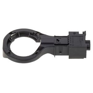 Optical Fiber Bypass Loop Connector
 - Disconnect the optical fiber connectors from one of the modules on the bus.
- Insert the bypass loop connector into the disconnected connectors.
- Use VCDS to check if communication has been restored on the bus.
- Repeat steps 2-4 for each module on the bus until the break is located.
3.8 Analyzing Live Data from Optical Bus Modules
VCDS allows technicians to view live data from modules connected to the optical bus, providing valuable insights into their performance. By analyzing this data, technicians can identify potential problems and diagnose issues that may not be apparent from DTCs alone.
- Select the module you want to analyze from the Auto-Scan results.
- Click on “Measuring Blocks” or “Advanced Measuring Values” to access live data.
- Select the data parameters you want to monitor and observe their values.
- Compare the values to the expected ranges and note any discrepancies.
4. Common Issues and Troubleshooting Tips
Diagnosing optical bus systems can be challenging, as the symptoms can be subtle and the underlying causes complex. However, by understanding common issues and employing effective troubleshooting techniques, technicians can successfully resolve most optical bus problems.
4.1 Identifying Common Symptoms of Optical Bus Problems
Several symptoms may indicate a problem with the optical bus system:
- Loss of audio or video functionality in the infotainment system.
- Navigation system malfunctions.
- Communication errors between modules.
- Intermittent or complete failure of certain vehicle functions.
- DTCs related to optical bus communication.
4.2 Diagnosing Fiber Optic Cable Issues
Fiber optic cables are susceptible to damage, which can disrupt communication on the optical bus. When the fiber cables are broken or roughly handled, the optical cables themselves will be the cause of the fault.
- Visually inspect the cables for any signs of damage, such as cracks, kinks, or cuts.
- Check the connectors for proper seating and ensure they are free from dirt and debris.
- Use an optical fiber tester to measure the light transmission through the cable.
- Replace any damaged cables or connectors.
4.3 Troubleshooting Module Communication Problems
Module communication problems can arise due to various factors, including faulty modules, software glitches, or wiring issues.
- Verify that all modules are properly connected to the optical bus.
- Check the power and ground connections to each module.
- Update the software on the modules to the latest version.
- Replace any faulty modules.
4.4 Resolving Software and Configuration Issues
Software and configuration issues can also cause problems with optical bus systems.
- Ensure that all modules are properly coded and adapted to the vehicle.
- Check for any software conflicts or incompatibilities.
- Re-flash the modules with the correct software if necessary.
- Consult the vehicle’s service manual for specific configuration requirements.
4.5 Addressing Electrical Faults in MOST Bus Systems
The MOST fault may be electrical. The fault could be in the ring-break-diagnostic wires that form the hub-and-spoke topology. Go to Start ring break diagnostics in the module Live Data function and initiate the procedure.
5. Advanced VCDS Techniques for Optical Bus Diagnostics
Beyond the basic diagnostic procedures, VCDS offers several advanced techniques that can help technicians diagnose and resolve complex optical bus problems.
5.1 Utilizing Adaptation and Coding for Module Configuration
VCDS allows technicians to modify the adaptation and coding settings of individual modules, enabling them to customize the vehicle’s behavior and resolve configuration issues.
- Select the module you want to configure from the Auto-Scan results.
- Click on “Coding” or “Adaptation” to access the configuration settings.
- Modify the settings as needed, following the on-screen instructions and consulting the vehicle’s service manual.
- Test the changes to ensure they have the desired effect.
5.2 Performing Firmware Updates on Optical Bus Modules
Keeping the firmware on optical bus modules up-to-date is essential for ensuring optimal performance and compatibility. VCDS can be used to perform firmware updates on many VAG vehicles.
- Check for available firmware updates for the modules on the optical bus.
- Download the updates from a reputable source.
- Use VCDS to flash the new firmware onto the modules, following the on-screen instructions carefully.
- Verify that the updates have been installed successfully and that the modules are functioning correctly.
5.3 Using VCDS Logs for In-Depth Analysis
VCDS can generate detailed logs of diagnostic sessions, which can be invaluable for analyzing complex problems and identifying intermittent faults.
- Enable logging in VCDS before starting the diagnostic session.
- Perform the diagnostic procedures as usual.
- Review the log file to identify any patterns or anomalies.
- Use the log data to pinpoint the source of the problem and develop a targeted solution.
6. Maintaining Optical Bus Systems for Optimal Performance
Proper maintenance is essential for ensuring the long-term reliability and performance of optical bus systems. By following these guidelines, technicians can help prevent problems and keep these systems functioning optimally.
6.1 Best Practices for Handling Fiber Optic Cables
Fiber optic cables are delicate and require careful handling to avoid damage.
- Avoid bending or kinking the cables excessively.
- Protect the cables from sharp objects and extreme temperatures.
- Keep the connectors clean and free from dirt and debris.
- Use appropriate tools when disconnecting or connecting the cables.
6.2 Preventing Connector Corrosion and Damage
Connector corrosion and damage can disrupt communication on the optical bus.
- Inspect the connectors regularly for signs of corrosion or damage.
- Clean the connectors with a suitable electronic cleaner.
- Apply dielectric grease to the connectors to prevent corrosion.
- Replace any damaged connectors.
6.3 Regular Software Updates and Module Recoding
Keeping the software on optical bus modules up-to-date and ensuring proper module coding is crucial for optimal performance.
- Check for software updates regularly and install them as needed.
- Verify that all modules are properly coded and adapted to the vehicle.
- Consult the vehicle’s service manual for specific coding requirements.
7. The Future of Optical Bus Diagnostics
As automotive technology continues to evolve, optical bus systems are likely to become even more complex and sophisticated. Staying ahead of these advancements will require technicians to continuously update their knowledge and skills.
7.1 Emerging Trends in Automotive Networking
Several emerging trends are shaping the future of automotive networking:
- Increased use of Ethernet-based networks for higher bandwidth and faster communication speeds.
- Adoption of advanced security protocols to protect against cyberattacks.
- Integration of wireless communication technologies for over-the-air updates and remote diagnostics.
- Development of more sophisticated diagnostic tools and techniques.
7.2 The Role of Artificial Intelligence in Diagnostics
Artificial intelligence (AI) is playing an increasingly important role in automotive diagnostics. AI-powered diagnostic tools can analyze vast amounts of data to identify patterns and anomalies, helping technicians quickly pinpoint the source of complex problems.
7.3 Continuous Learning and Skill Development
To stay competitive in the rapidly evolving automotive industry, technicians must commit to continuous learning and skill development. This includes:
- Attending training courses and workshops.
- Staying up-to-date with the latest diagnostic tools and techniques.
- Networking with other technicians and sharing knowledge.
- Consulting online resources and forums.
8. Why Choose CARDIAGTECH.NET for Your Diagnostic Needs
At CARDIAGTECH.NET, we understand the challenges that automotive technicians face when diagnosing and repairing modern vehicles. That’s why we offer a comprehensive range of diagnostic tools, equipment, and support services to help you succeed.
8.1 Our Commitment to Quality and Innovation
We are committed to providing our customers with the highest quality diagnostic tools and equipment. We partner with leading manufacturers to ensure that our products meet the latest industry standards and offer cutting-edge features.
8.2 Our Comprehensive Range of Diagnostic Tools
We offer a wide range of diagnostic tools to meet the needs of every technician, from entry-level scan tools to advanced diagnostic systems. Our product lineup includes:
- VCDS (VAG-COM Diagnostic System)
- OBD-II scanners
- Multimeters
- Oscilloscopes
- Optical fiber testers
8.3 Expert Support and Training Services
We provide expert support and training services to help our customers get the most out of their diagnostic tools. Our team of experienced technicians is available to answer your questions and provide guidance on diagnosing and repairing complex vehicle systems.
9. Frequently Asked Questions (FAQs)
Here are some frequently asked questions about optical bus diagnostics with VCDS:
1. What is an optical bus system?
An optical bus system is a communication network that uses fiber optic cables to transmit data as light signals between modules in a vehicle.
2. What is VCDS?
VCDS (VAG-COM Diagnostic System) is a comprehensive diagnostic tool developed specifically for Volkswagen Audi Group (VAG) vehicles.
3. How does VCDS help with optical bus diagnostics?
VCDS can identify modules on the optical bus, read DTCs, perform output tests, check optical bus status, and utilize ring break diagnostics.
4. What are some common symptoms of optical bus problems?
Common symptoms include loss of audio or video functionality, navigation system malfunctions, communication errors, and intermittent failures.
5. How can I diagnose fiber optic cable issues?
Visually inspect cables, check connectors, and use an optical fiber tester to measure light transmission.
6. What is ring break diagnostics?
Ring break diagnostics is a VCDS function that helps pinpoint the location of a break in the optical bus ring by systematically bypassing each module.
7. How can I maintain optical bus systems for optimal performance?
Handle fiber optic cables carefully, prevent connector corrosion, and perform regular software updates.
8. What are the emerging trends in automotive networking?
Emerging trends include increased use of Ethernet, advanced security protocols, and integration of wireless communication.
9. How is artificial intelligence used in diagnostics?
AI-powered tools analyze data to identify patterns and anomalies, helping technicians quickly pinpoint complex problems.
10. Why should I choose CARDIAGTECH.NET for my diagnostic needs?
CARDIAGTECH.NET offers high-quality tools, a comprehensive product range, and expert support and training services.
10. Take Action Now
Don’t let optical bus problems slow you down. Contact CARDIAGTECH.NET today to learn more about our diagnostic tools and services. Our team of experts can help you find the right solutions for your needs and provide the support you need to succeed.
Contact us today:
- Address: 276 Reock St, City of Orange, NJ 07050, United States
- WhatsApp: +1 (641) 206-8880
- Website: CARDIAGTECH.NET
Take control of your diagnostic capabilities and unlock the full potential of your automotive repair business with CARDIAGTECH.NET.