Embarking on DIY automotive diagnostics can be both rewarding and cost-effective. For car enthusiasts and those keen on understanding their vehicle’s inner workings, creating an OBDII to USB cable is a fantastic starting point. This guide, brought to you by the experts at autelfrance.com, will walk you through the process of building your own OBDII to USB adapter, allowing you to interface with your car’s computer system using readily available tools and components.
Before we begin, it’s crucial to understand that this project is undertaken at your own risk. While we aim to provide a clear and accurate guide, autelfrance.com cannot be held responsible for any damage or issues that may arise from attempting this DIY project. Ensure you proceed with caution and a basic understanding of automotive electronics.
Tools and Parts You’ll Need
To successfully construct your Obdii To Usb Diy cable, gather the following tools and parts:
- Wire Strippers/Cutters: Essential for preparing the wires for connection.
- Needle-Nose Pliers: Useful for manipulating small components and wires.
- Molex Crimping Tool (Optional but Recommended): While not strictly necessary, a crimping tool ensures secure and professional-looking connections.
- Soldering Iron (Recommended): Soldering provides a robust and reliable connection, especially for delicate wires.
- 4-Pin Connector: This connector will interface with your chosen interface device. Ensure compatibility with your project needs.
- OBD-II Cable: This cable is crucial as it provides the OBD-II connector that plugs into your vehicle.
For the parts, consider sourcing a complete OBD-II cable as it contains the necessary OBD-II connector and wires. Alternatively, if you have spare wires and wish to minimize cost, you can purchase a female OBD-II connector separately and use your own wires to connect it to the 4-pin connector. If opting for separate components, ensure you select a 4-pin connector that is compatible with your wire gauge.
In this DIY guide, we will be focusing on utilizing just four essential wires from the 16 available in the OBD-II connector (referred to as OBD2C):
- Pin 4 (Chassis Ground): Typically an orange wire in the OBD2C.
- Pin 6 (CAN [J-2234] High): Usually a green wire in the OBD2C.
- Pin 14 (CAN [J-2234] Low): Often a brown wire with a white stripe in the OBD2C.
- Pin 16 (Battery Power): Commonly a green wire with a white stripe in the OBD2C.
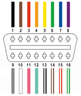 OBD-II Connector Pinout
Step-by-Step Guide to Building Your OBDII to USB DIY Cable
Let’s delve into the step-by-step process of constructing your OBDII to USB cable.
Step 1: Preparing the OBD-II Cable Wires
Begin by carefully stripping back the outer sheath and shielding of the OBD-II cable (OBD2C) to expose the individual wires inside. Identify and separate the four wires you’ll be using: Pin 4 (orange), Pin 6 (green), Pin 14 (brown with white stripe), and Pin 16 (green with white stripe). To keep the unused wires out of the way, neatly bundle them together and secure them with a zip tie.
 Stripped sheath and shielding of OBD-II Cable
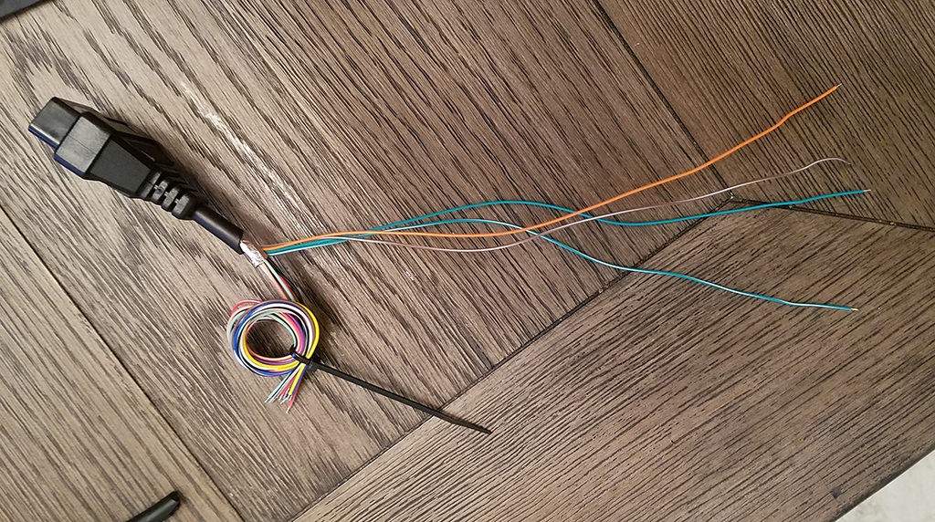 Separated Wires for OBDII to USB DIY
Step 2: Preparing the Wires for the 4-Pin Connector
A potential challenge you might encounter is the gauge difference between the OBD2C wires (typically 26AWG) and the pins of the 4-pin connector (designed for 22AWG). The OBD2C wires are thinner, so to ensure a secure connection, we need to thicken them slightly.
The wires usually come pre-stripped with a small amount of exposed wire (around 1/8 inch). Carefully strip off more insulation until approximately 3/8 inch of wire is exposed. To increase the wire thickness, fold the exposed wire over itself and twist the strands together tightly. This will create a thicker wire that fits better within the 4-pin connector pins.
Before proceeding with the connection, slide a rubber seal (provided with the 4-pin connector kit) onto each of the four prepared wires. These seals provide environmental protection and strain relief for the connections.
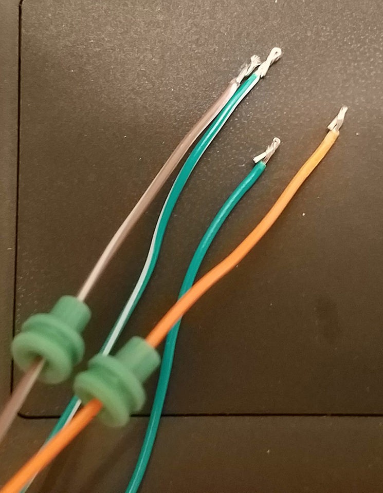 Preparing wires and rubber seals for 4-Pin Connector
Step 3: Attaching Wires to 4-Pin Connector Pins
Examine the pins of the 4-pin connector. You’ll notice two sets of prongs. The front prongs are designed to crimp onto the exposed wire, while the rear prongs crimp onto the rubber seal, providing strain relief.
Insert the prepared and thickened wire into the front of the pin, ensuring the exposed wire aligns with the front set of prongs. Due to the small gauge of the wire compared to the pin, using needle-nose pliers to hold the wire in place during the next step is highly recommended. This ensures precise alignment and facilitates a secure connection.
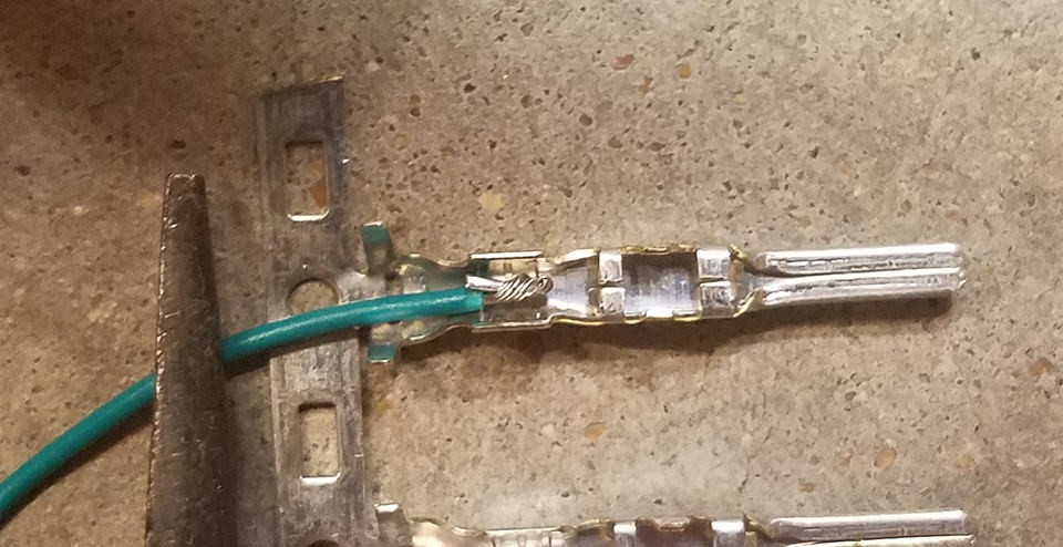 Wire inserted into 4-Pin Connector Pin
Step 4: Soldering the Wire to the Pin Connector (Recommended)
For a robust and electrically sound connection, soldering the wire to the pin connector is highly advisable. Soldering creates a permanent bond and ensures excellent conductivity. If you are new to soldering, numerous online resources, such as YouTube tutorials, can provide valuable guidance on soldering techniques.
Apply a small amount of solder to the point where the wire meets the pin connector. Ensure the solder flows smoothly and creates a solid joint. While soldering skills improve with practice, even a basic solder joint will significantly enhance the reliability of your OBDII to USB DIY cable.
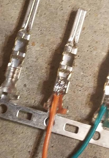 Soldering Wire to Pin Connector
Step 5: Crimping the Connector (Alternative to Soldering)
If you possess a Molex crimping tool, this step becomes straightforward. Position the pin with the wire in the crimping tool and gently crimp the front prongs around the exposed wire. The crimping tool ensures the prongs are evenly and securely fastened, creating a gas-tight connection.
For those without a crimping tool, needle-nose pliers can be used as an alternative. Using the pliers at an angle, carefully fold one of the front prongs over the wire. Repeat this for the other prong, ensuring both prongs are tightly crimped. While this method requires more finesse, it can effectively secure the wire within the pin connector. For enhanced security, you can further compress the crimped prongs with the pliers, though this might be considered overkill for most applications.
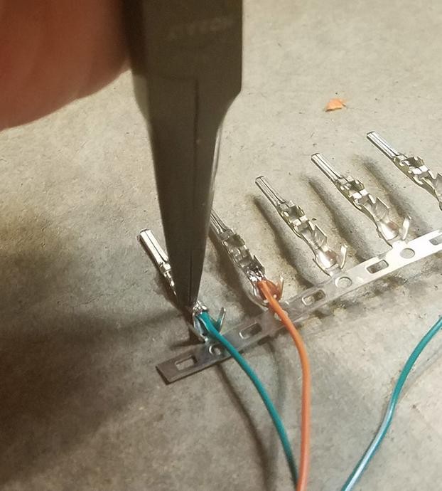 Crimping Pin Connector with Pliers
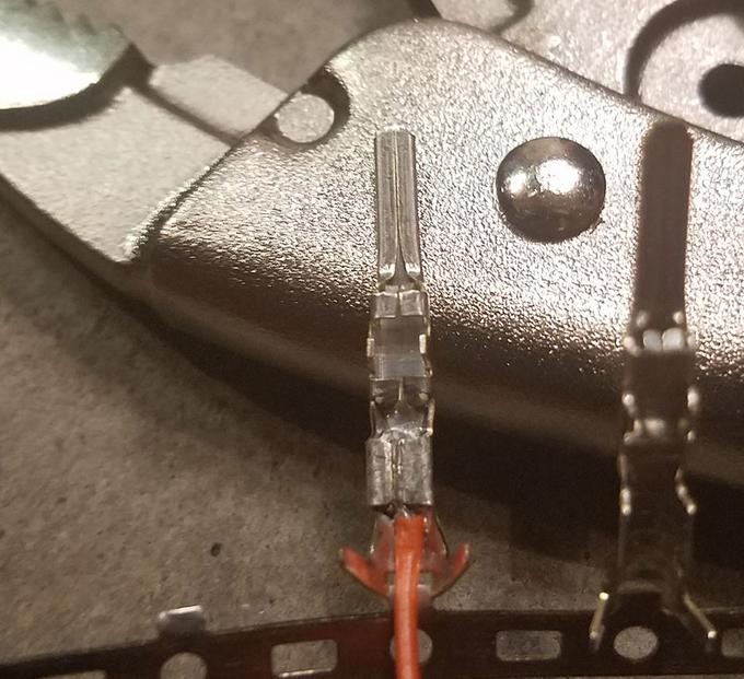 Crimped Pin Connector Detail
Step 6: Crimping the Seal Prongs
Slide the rubber seal up the wire until it sits snugly between the rear set of prongs on the pin connector. Employ the same crimping technique used in Step 5 (either with a crimping tool or needle-nose pliers) to fold the rear prongs over the rubber seal. This secures the seal in place and provides strain relief, preventing the wire from being easily pulled out and protecting the connection from environmental factors.
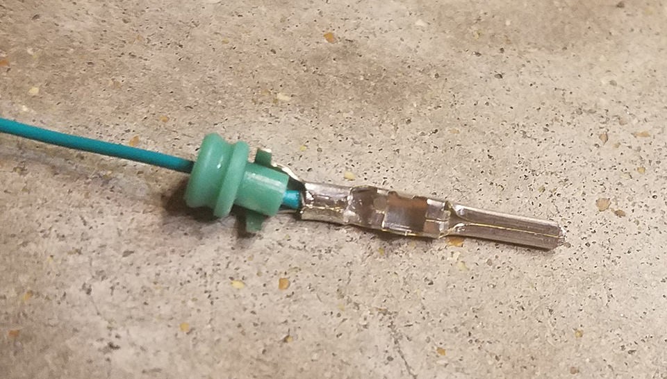 Crimping Seal Prongs – Step 1
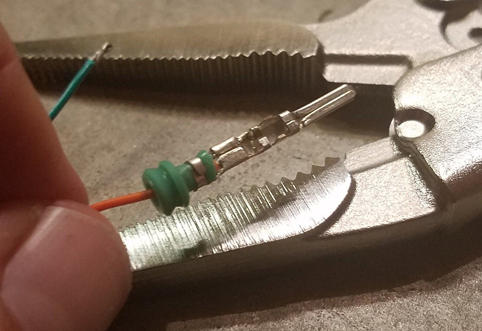 Crimping Seal Prongs – Step 2
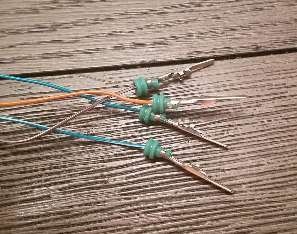 Crimped Seal Prongs Detail
Step 7: Wire Pairing and Twisting
While the exact reason isn’t definitively established, many DIY guides recommend pairing and twisting certain wires together. This practice might offer some level of noise reduction or signal integrity improvement. Pair and twist the wires as follows:
- Pin 4 (orange) / Pin 16 (green w/white stripe)
- Pin 6 (green) / Pin 14 (brown w/white stripe)
While a photo of this step isn’t available, simply twisting each pair of wires together a few times is sufficient.
Step 8: Inserting Pins into the 4-Pin Connector Housing
Finally, insert the pins into the 4-pin connector housing in the correct orientation. Refer to the diagram below for the proper pin placement:
- Pin 14 (brown w/white stripe): Connector slot A
- Pin 6 (green): Connector slot B
- Pin 16 (green w/white stripe): Connector slot C
- Pin 4 (orange): Connector slot D
Push each pin into the rear of the connector housing until you hear an audible “click.” This click indicates that the pin is securely locked into place. Using needle-nose pliers to gently pull on each wire after insertion can confirm they are indeed locked and secure within the connector.
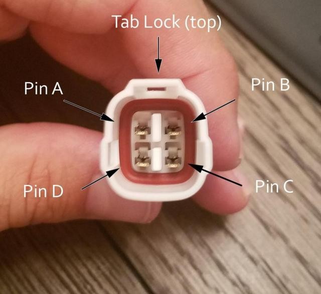 4-Pin Connector Pin Orientation
Completion and Testing
Congratulations! Your OBDII to USB DIY cable is now complete.
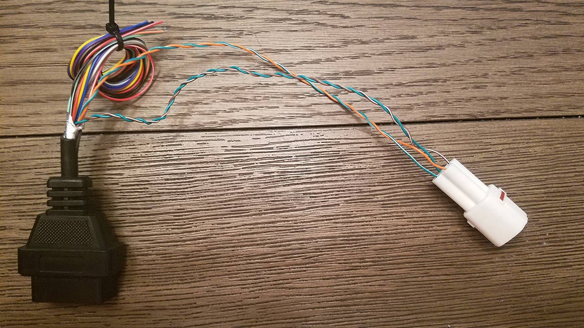 Completed OBDII to USB DIY Cable
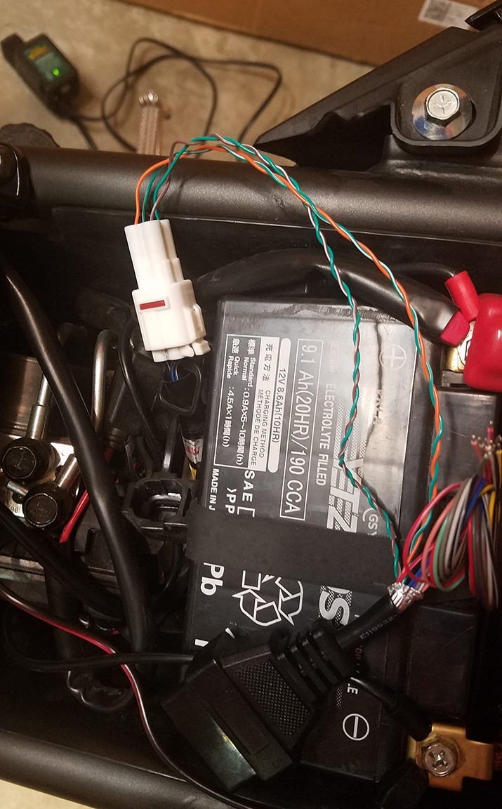 OBDII to USB DIY Cable – Close Up
To ensure your newly constructed cable functions correctly, test it by connecting it to your vehicle and a compatible diagnostic tool or software. Successfully testing and clearing a diagnostic error (even a self-induced one for testing purposes) confirms the cable’s functionality.
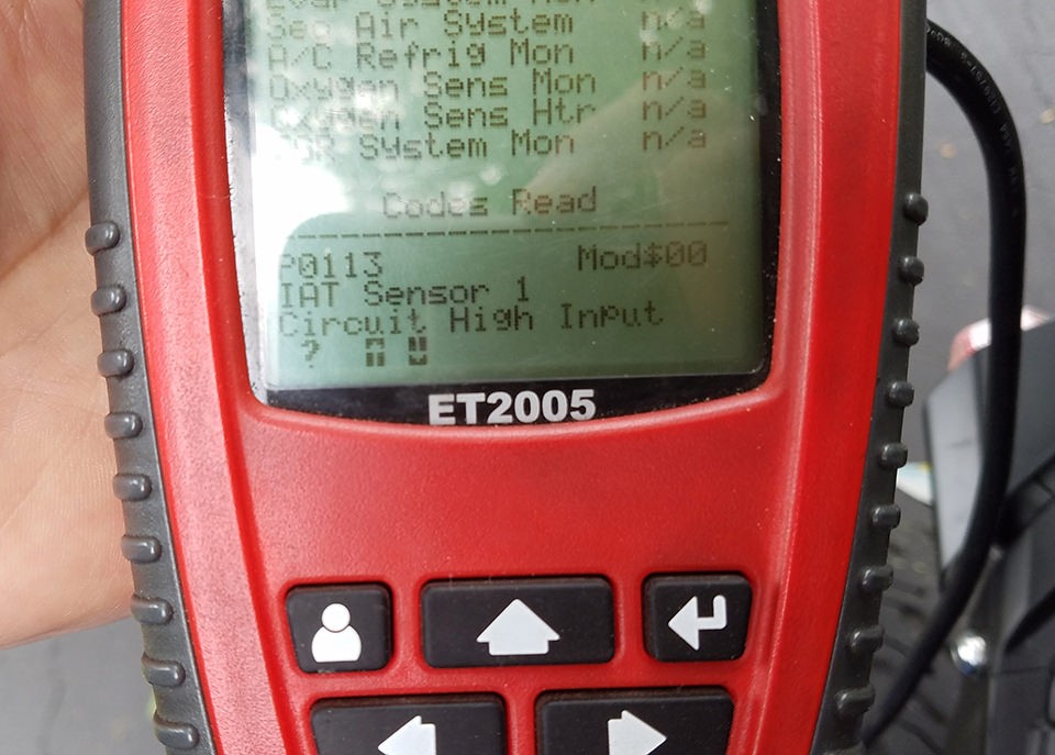 OBDII to USB DIY Cable in Use
If any step in this guide is unclear or requires further explanation, feel free to seek clarification or request additional photos for better understanding. With patience and careful execution, building your own OBDII to USB DIY cable is an achievable and insightful project for any automotive enthusiast.
