Understanding OBDII protocols is crucial for effective vehicle diagnostics and repair. Since 1996, all cars and light trucks sold in the United States have been mandated to be OBD-II compliant. The European Union’s OBD legislation, while more intricate, also necessitates compliance. This standardization ensures that regardless of the manufacturer, diagnostic tools can communicate with a vehicle’s computer system. However, the communication methods, or protocols, can vary. This guide will delve into the different OBDII protocols employed by manufacturers, providing essential knowledge for automotive professionals.
OBD-II compliant vehicles utilize one of five primary communication protocols: J1850 PWM, J1850 VPW, ISO9141-2, ISO14230-4 (Keyword Protocol 2000), and the more contemporary ISO15765-4/SAE J2480 (CAN). It’s important to note that while CAN protocol is now universally adopted in vehicles from model year 2008 onwards in the US, earlier models and vehicles from different regions may use a variety of these protocols. Initially, US car manufacturers were restricted from using CAN until model year 2003, leading to a diverse landscape of protocol implementation across different makes and models.
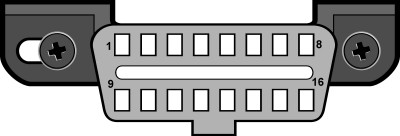
To physically interface with a vehicle’s diagnostic system, the Society of Automotive Engineers (SAE) J1962 standard defines two types of Diagnostic Link Connectors (DLCs): Type A and Type B. These connectors, illustrated in Figures 1 and 2, primarily differ in the shape of their alignment tab, but both serve the same purpose of providing a standardized access point for diagnostic tools.
 Type A J1962 Vehicle Connector Diagram
Fig. 1 – Type A J1962 Vehicle Connector, commonly found in OBDII compliant vehicles.
The SAE J1962 standard also dictates the location of the Type A DLC. It “shall be located in the passenger or driver’s compartment in the area bounded by the driver’s end of the instrument panel to 300 mm (~1 ft) beyond the vehicle centerline, attached to the instrument panel and easy to access from the driver’s seat. The preferred location is between the steering column and the vehicle centerline.” This standardized location ensures ease of access for technicians.
Type B DLCs, according to J1962, offer more flexibility in placement. They “shall be located in the passenger or driver’s compartment in the area bounded by the driver’s end of the instrument panel, including the outer side, and an imagined line 750 mm (~2.5 ft) beyond the vehicle centerline. It shall be attached to the instrument panel and easy to access from the driver’s seat or from the Co-drivers seat or from the outside. The vehicle connector shall be mounted to facilitate mating and unmating.” This allows for integration in various vehicle designs and accessibility needs.
 Type B J1962 Vehicle Connector Diagram
Fig. 2 – Type B J1962 Vehicle Connector, an alternative design for OBDII diagnostic interfaces.
Determining the specific OBDII protocol a vehicle uses can often be achieved by examining the pinout of the DLC. Figure 3 provides a detailed pinout diagram of the J1962 OBDII connector, which is instrumental in identifying the communication protocol.
 J1962F OBDII Connector Pinout Diagram
Fig. 3 – OBDII connector pinout diagram, essential for protocol identification based on pin assignments.
The table below clarifies how to ascertain the protocol based on which pins are populated in the DLC. This is a practical method for technicians to quickly identify the communication protocol without needing specialized tools in some cases.
| Pin 2 | Pin 6 | Pin 7 | Pin 10 | Pin 14 | Pin 15 | Standard |
|---|---|---|---|---|---|---|
| must have | – | – | must have | – | – | J1850 PWM |
| must have | – | – | – | – | – | J1850 VPW |
| – | – | must have | – | – | may have* | ISO9141/14230 |
| – | must have | – | – | must have | – | ISO15765 (CAN) |
*Pin 15 (L-line) is optional in newer vehicles utilizing ISO9141-2 or ISO14230-4 protocols.
In addition to these protocol-specific pins, certain pins are mandatory for all OBDII compliant vehicles. Pins 4 (Chassis Ground), 5 (Signal Ground), and 16 (Battery Positive) should always be present in the connector, regardless of the communication protocol.
This leads to a simplified view of pin requirements for each protocol, further aiding in quick identification:
| Protocol | Pin Requirements |
|---|---|
| PWM | Pins 2, 4, 5, 10, and 16 must be present |
| VPW | Pins 2, 4, 5, and 16 must be present, but not 10 |
| ISO | Pins 4, 5, 7, and 16 must be present. Pin 15 may or may not be present. |
| CAN | Pins 4, 5, 6, 14, and 16 must be present |
For more detailed information and manufacturer-specific OBDII protocol implementation, resources like the OBDII Generic Communication Protocols by Manufacturer provide invaluable insights. Understanding these nuances is essential for accurate diagnostics and efficient automotive repairs.
In conclusion, while OBDII standardization provides a universal diagnostic interface, the underlying communication protocols can vary. Recognizing these protocols and how to identify them via DLC pinouts is a fundamental skill for any automotive technician. With the automotive industry’s move towards Controller Area Network (CAN) as the dominant protocol, familiarity with ISO15765-4 is increasingly important, yet understanding legacy protocols remains relevant for servicing older vehicles.

