Building your own OBD-II connector harness can be a rewarding DIY project, especially when you need a custom setup for vehicle diagnostics or specific electronic integrations. This guide provides a step-by-step approach to wiring an OBD-II connector, focusing on Pin 16 for power and its crucial role in establishing a functional diagnostic link. Please remember, this is a guide based on personal experience and is intended for informational purposes. Proceed at your own risk, as incorrect wiring can potentially damage your vehicle’s electronics.
Tools You’ll Need:
- Wire strippers/cutters
- Needle-nose pliers
- Molex crimping tool (optional, but recommended for professional results)
- Soldering iron and solder (recommended for robust connections)
Parts Required:
- 4-Pin Connector (suitable for 22-16AWG wire, 1.3-1.7mm insulation/seal size)
- OBD-II Cable (with a female OBD-II connector)
For cost-effectiveness, if you have spare automotive wire, you can purchase a standalone female OBD-II connector and wire. Ensure your wire gauge is compatible with the 4-pin connector specifications.
From the 16 pins available on a standard OBD-II connector (OBD2C), we will only be utilizing four essential wires for basic diagnostic and power functions:
- Pin 4: Chassis Ground (typically an orange wire on the OBD2C)
- Pin 6: CAN High (J-2234) for communication (typically a green wire on the OBD2C)
- Pin 14: CAN Low (J-2234) for communication (typically a brown wire with a white stripe on the OBD2C)
- Pin 16: Battery Power (12V) – This is our key focus, often referred to in the context of “Obdii Pairing Code 16” as it provides the necessary power for many OBD-II devices. (typically a green wire with a white stripe on the OBD2C)
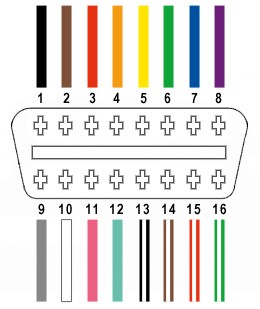 Diagram highlighting OBD-II connector pins including pin 16 for battery power
Step-by-Step Wiring Guide
1. Preparing the OBD-II Cable Wires:
It’s good practice to twist pairs of wires for signal integrity, especially for CAN bus communication. Begin by carefully removing the outer sheath and shielding from the OBD-II cable to access the internal wires. Identify and separate the four wires you will be using: Pin 4 (Ground), Pin 6 (CAN High), Pin 14 (CAN Low), and Pin 16 (Power). Bundle the remaining 12 wires and secure them out of the way with a zip tie to keep your workspace tidy.
 OBD-II cable with sheath and shielding removed to expose internal wires
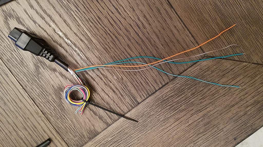 Separated wires from OBD-II cable, isolating the four essential wires for the harness
2. Preparing Wires for the 4-Pin Connector:
The wires in the OBD-II cable are often a finer 26AWG gauge, while the pins for the 4-pin connector (4PC) are designed for slightly thicker 22AWG wire. To ensure a secure connection, we need to increase the wire thickness slightly. The OBD-II cable wires usually come pre-stripped with about 1/8″ of exposed wire. Carefully strip an additional 1/4″ to get approximately 3/8″ of exposed wire. Fold this exposed wire over itself to double its thickness and then twist the folded wire to create a more substantial gauge that fits better within the 4-pin connector pins. Slide a rubber seal (from the 4PC kit) onto each of the four prepared wires. These seals provide environmental protection at the connector.
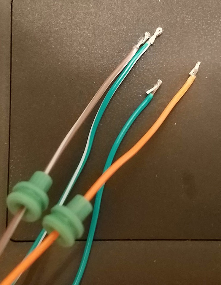 Close-up of OBD-II cable wire with insulation stripped and rubber seal ready for pin insertion
3. Inserting Wires into 4-Pin Connector Pins:
Examine the pins for the 4-pin connector. You’ll notice two sets of prongs. The inner set is designed to crimp onto the exposed wire, providing electrical contact, and the outer set crimps onto the wire insulation/seal for strain relief and environmental sealing. Insert the prepared and folded wire into the pin, ensuring it aligns with the inner set of prongs. The wire gauge might appear small relative to the pin size, as shown in the image. Using needle-nose pliers can help hold the wire securely in place during the next step, especially given the fine gauge of the wire.
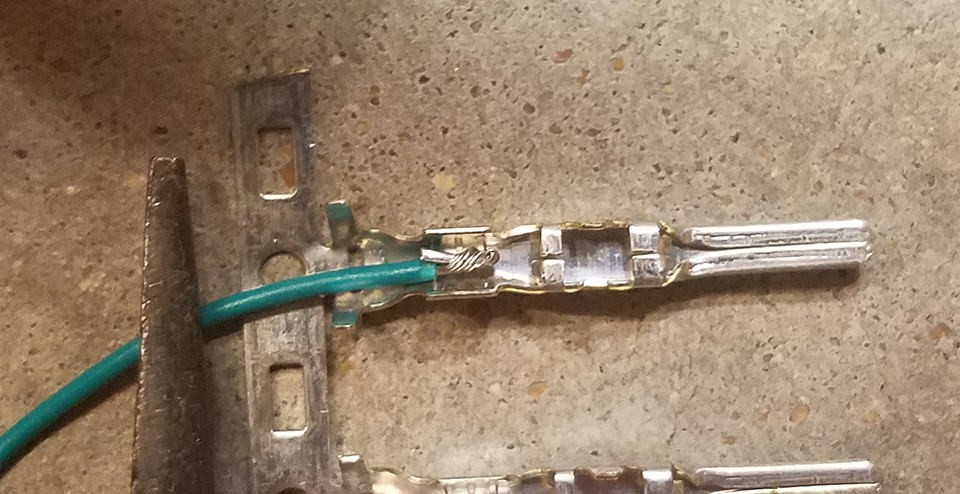 Image showing the small gauge wire inserted into the larger 4-pin connector pin, highlighting the need for secure crimping or soldering
4. Soldering Wire to Connector Pin (Recommended):
Soldering provides a very reliable and robust electrical and mechanical connection, which is highly recommended, especially when working with finer gauge wires. If you are comfortable with soldering, apply a small amount of solder to the area where the wire is inserted into the pin. This will create a solid bond and ensure excellent conductivity. If soldering isn’t your preference or you lack the equipment, skip to step 5 for crimping instructions.
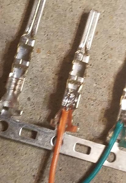 Soldering the wire to the 4-pin connector pin for a secure and conductive connection
5. Crimping Wire to Connector Pin (Alternative Method):
If you have a Molex crimping tool, this is the ideal method for securing the wire to the pin. Position the pin and wire in the crimping tool according to the tool’s instructions and crimp firmly. If you don’t have a specialized crimping tool, needle-nose pliers can be used as an alternative. Carefully use the pliers at an angle to fold one prong of the inner set over the exposed wire. Repeat for the other prong, ensuring a tight crimp. You can find helpful videos online demonstrating crimping techniques with pliers. For added security, you can further compress the crimped prongs with pliers, though be careful not to damage the pin.
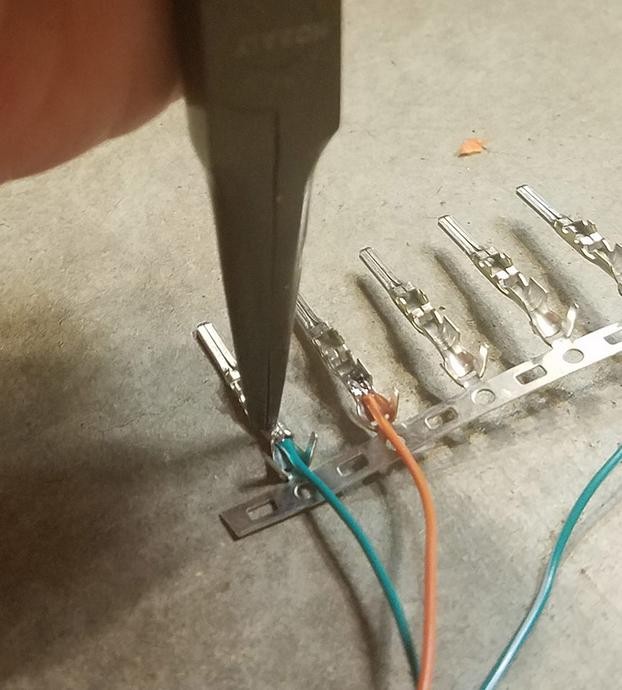 Crimping the inner prongs of the 4-pin connector pin onto the wire using pliers as an alternative to a crimping tool
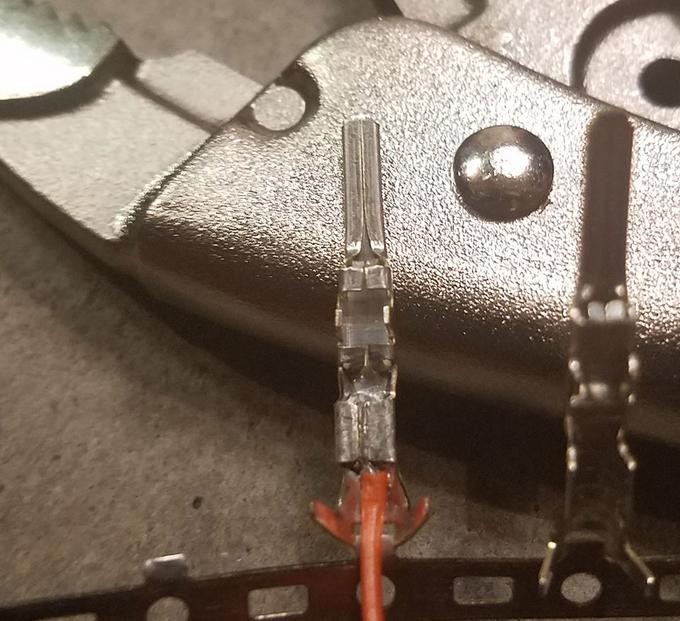 Close-up of the inner prongs crimped down onto the wire, securing the electrical connection
6. Crimping Insulation Seal:
Slide the rubber seal up the wire until it sits between the outer set of prongs on the 4-pin connector pin. Use the same crimping technique as in step 5 (either with a crimping tool or needle-nose pliers) to fold these outer prongs over the rubber seal. This crimp provides strain relief, secures the seal, and helps protect the connection from moisture and contaminants.
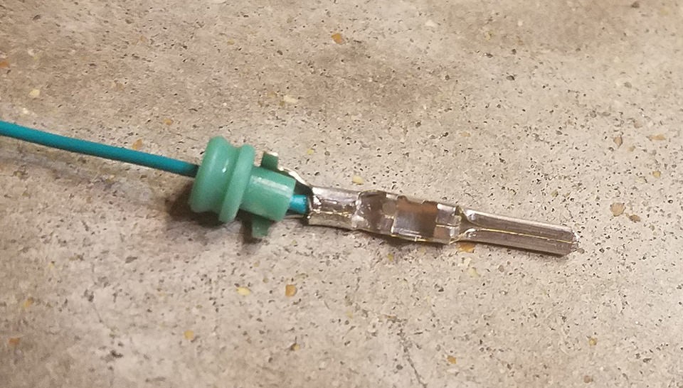 Positioning the rubber seal between the outer prongs of the 4-pin connector pin in preparation for crimping
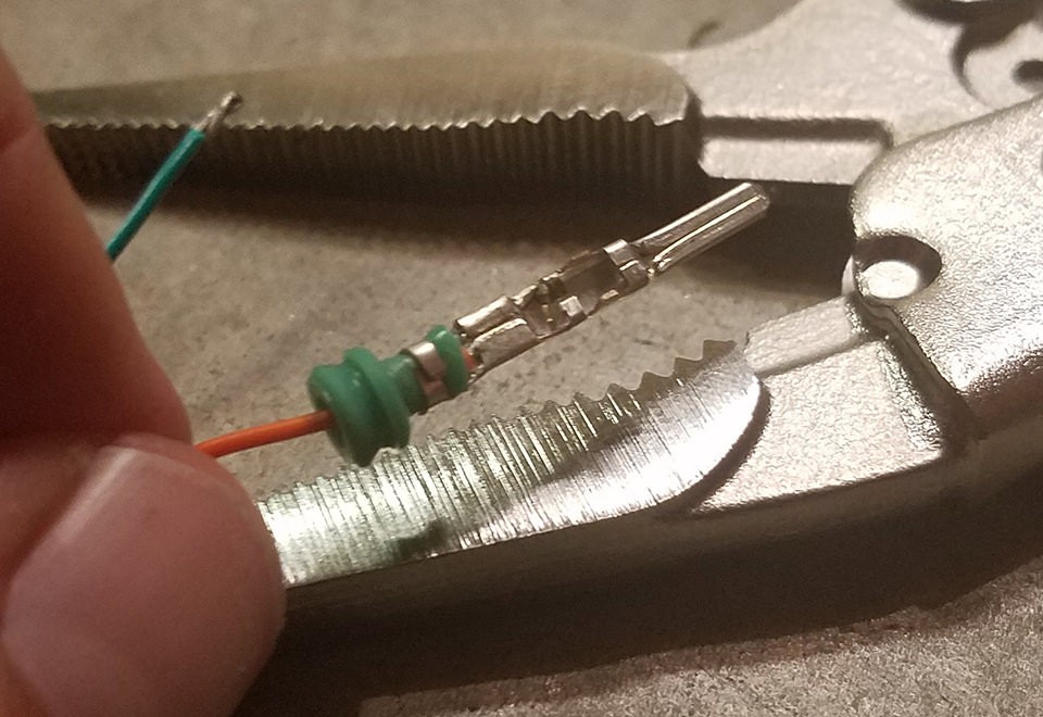 Crimping the outer prongs over the rubber seal to secure the insulation and provide strain relief
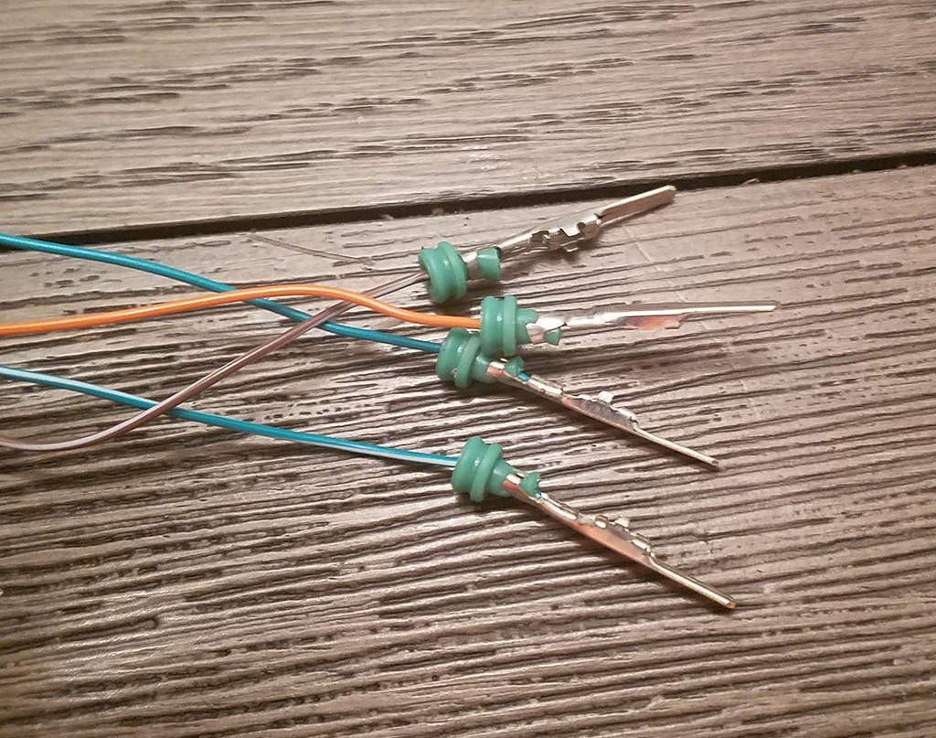 Completed crimping of both wire and insulation prongs on the 4-pin connector pin
7. Wire Pairing and Twisting:
For improved signal quality, especially for CAN bus communication, it is recommended to twist specific wire pairs together. Pair the wires as follows:
- Pin 4 (Orange – Ground) / Pin 16 (Green w/ White Stripe – Power) – This pairing includes Pin 16, crucial for OBD-II device power.
- Pin 6 (Green – CAN High) / Pin 14 (Brown w/ White Stripe – CAN Low) – This pairing is essential for CAN communication.
Twist each pair of wires together along their length. This helps reduce electromagnetic interference and ensures cleaner signal transmission.
8. Inserting Pins into the 4-Pin Connector Housing:
Insert the completed pins into the 4-pin connector housing in the correct orientation. Refer to the pinout diagram below:
- Connector Slot A: Pin 14 (Brown w/ White Stripe – CAN Low)
- Connector Slot B: Pin 6 (Green – CAN High)
- Connector Slot C: Pin 16 (Green w/ White Stripe – Power) – Pin 16 placement for power.
- Connector Slot D: Pin 4 (Orange – Ground)
Push each pin into the rear of the connector housing until you hear a distinct “click.” This click indicates that the pin is securely locked into place. Using needle-nose pliers can sometimes help to gently pull the wire from the front to ensure the pin is fully seated and locked.
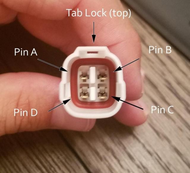 Diagram showing the correct pin insertion order into the 4-pin connector housing, including pin 16 in slot C
Your DIY OBD-II Connector Harness is Complete!
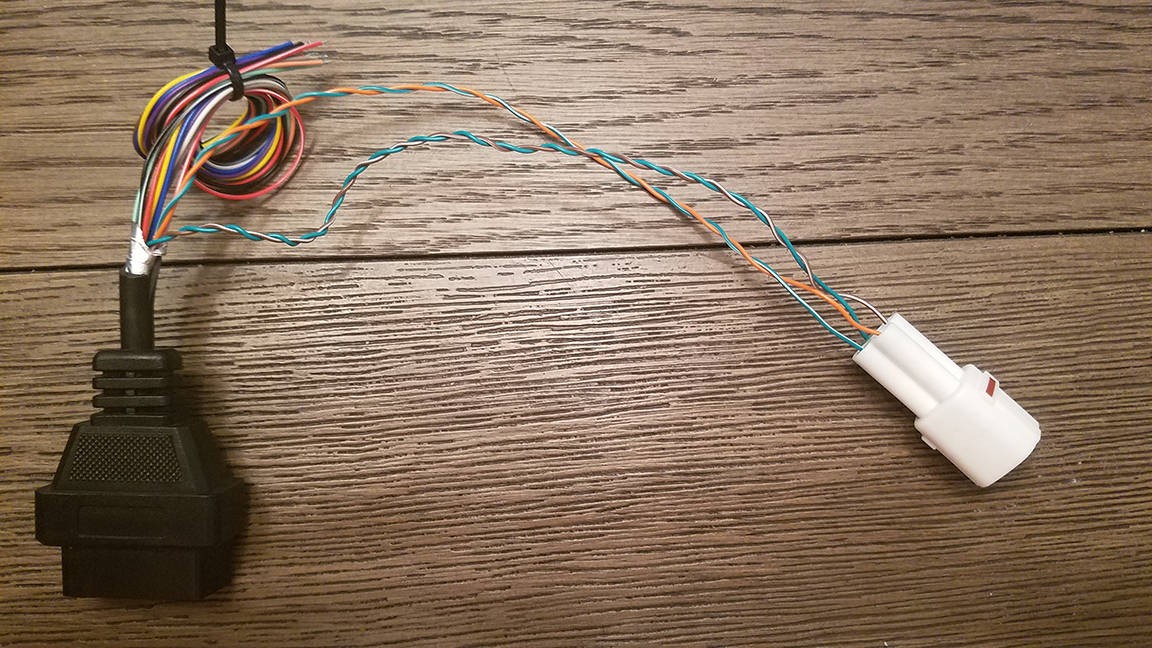 Completed DIY OBD-II connector harness with 4-pin connector
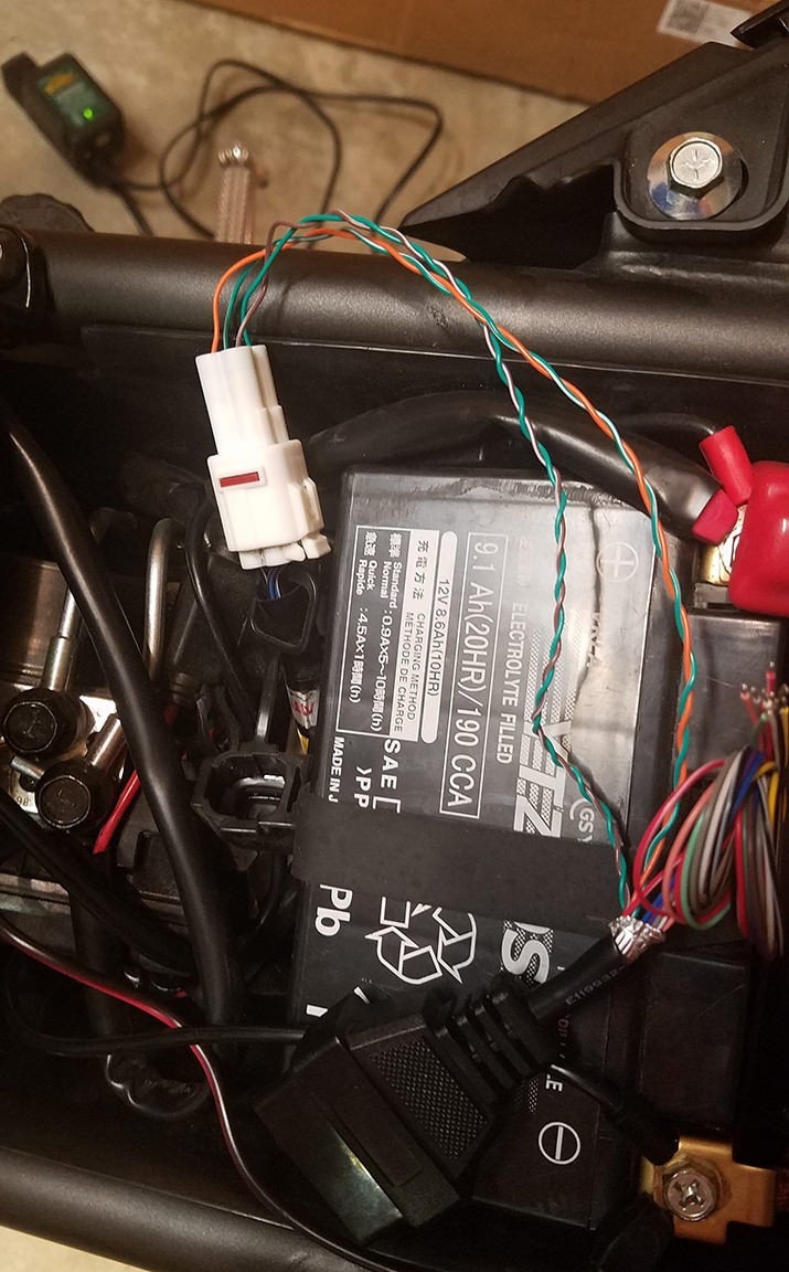 Close-up view of the finished OBD-II connector and 4-pin connector assembly
This custom-built OBD-II harness is now ready for use. It has been tested and confirmed to successfully read and clear diagnostic trouble codes.
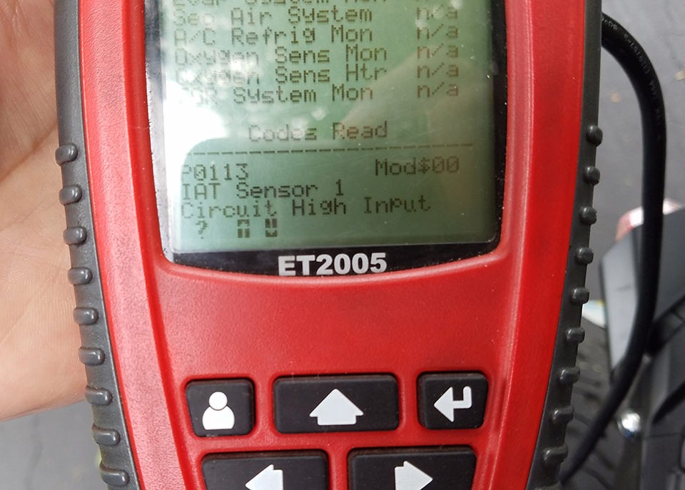 Screenshot showing successful OBD-II connection and error clearing using the DIY harness
If any step in this guide is unclear or requires further explanation, please ask for clarification. Additional photos or more detailed instructions can be provided. Enjoy the functionality of your newly created OBD-II harness!
