
Looking for a detailed yet accessible explanation of the OBDII protocol?
This guide offers an in-depth exploration of the On-Board Diagnostics II (OBDII) protocol, with a special focus on its integration with the ISO CAN bus protocol. We will delve into the OBDII connector, OBDII Parameter IDs (PIDs), and the crucial link between OBDII and the Controller Area Network (CAN) bus, specifically the Obdii Iso Canbus Protocol.
This is more than just an introduction; it’s a practical guide designed to elevate your understanding. You’ll learn how to effectively request and interpret OBDII data, discover key use cases for data logging, and gain valuable practical tips for working with the obdii iso canbus protocol.
Discover why this article is rapidly becoming the go-to resource for mastering the obdii iso canbus protocol.
You can also enhance your learning with our introductory video on OBDII, or download a comprehensive PDF guide on CAN bus for offline access.
Article Contents:
Author: Martin Falch (Expert in Automotive Diagnostics) (Updated January 2025)
Download as PDF
Understanding OBDII: The Basics
OBDII, or On-Board Diagnostics II, serves as your vehicle’s integrated self-diagnostic system. It’s a standardized protocol that enables the retrieval of diagnostic trouble codes (DTCs) and real-time vehicle data through the OBDII connector, leveraging the obdii iso canbus protocol.
You’re likely already familiar with OBDII in some form. Have you ever noticed the malfunction indicator light, commonly known as the “check engine light,” illuminating on your dashboard?
That light is your vehicle signaling a potential issue. When you take your car to a mechanic, they use an OBDII scanner to pinpoint the problem.
This process involves connecting an OBDII reader to the 16-pin OBDII connector, typically located near the steering wheel. The scanner transmits ‘OBDII requests’ to the car’s computer, and the car responds with ‘OBDII responses.’ These responses can contain vital information such as speed, fuel level, or Diagnostic Trouble Codes (DTCs), enabling mechanics to diagnose and resolve issues more efficiently using the obdii iso canbus protocol.
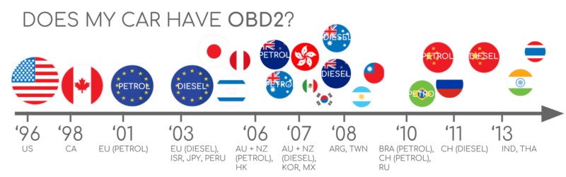
OBDII Compatibility: Does Your Car Support It?
The short answer is: Almost certainly!
The vast majority of modern non-electric vehicles are OBDII compliant, and most of these utilize the CAN bus system as part of their obdii iso canbus protocol implementation. For older vehicles, even if a 16-pin OBDII connector is present, it might not necessarily support the OBDII protocol fully. To confirm compatibility, consider the vehicle’s origin and year of purchase:
A Brief History of OBDII and the Rise of the ISO CAN Bus Protocol
OBDII’s roots are in California, where the California Air Resources Board (CARB) mandated OBD systems in all new vehicles from 1991 onwards for emissions monitoring. This early OBD system paved the way for the standardized obdii iso canbus protocol.
The OBDII standard was developed further by the Society of Automotive Engineers (SAE), which standardized DTCs and the OBD connector across different manufacturers (SAE J1962). This standardization was crucial for the widespread adoption of the obdii iso canbus protocol.
The OBDII standard was implemented gradually worldwide:
- 1996: OBDII became mandatory in the USA for cars and light trucks.
- 2001: The European Union required OBDII for gasoline vehicles.
- 2003: The EU extended the requirement to diesel vehicles (EOBD), further solidifying the obdii iso canbus protocol in Europe.
- 2005: OBDII was mandated in the US for medium-duty vehicles.
- 2008: US regulations required vehicles to use ISO 15765-4 (CAN) as the foundation for OBDII, marking the definitive adoption of the obdii iso canbus protocol.
- 2010: OBDII compliance became mandatory for heavy-duty vehicles in the US.
The Future of OBDII and the Evolving Landscape of Automotive Diagnostics
OBDII is firmly established, but its future is evolving.
Here are some key trends shaping the future of OBDII and the obdii iso canbus protocol:
Originally designed for emissions control, legislated OBDII is not strictly required for electric vehicles. Consequently, most modern EVs do not support standard OBDII requests. Instead, they often utilize OEM-specific UDS communication protocols. This shift makes accessing data from EVs challenging unless decoding rules are reverse-engineered. However, there are successful case studies for electric vehicles including Tesla, Hyundai/Kia, Nissan and VW/Skoda EVs.
Current OBDII implementations have limitations in data richness and lower-layer protocols. In response, advanced alternatives like WWH-OBD (World Wide Harmonized OBD) and OBDonUDS (OBD on UDS) have emerged. These protocols aim to enhance OBD communication by using the UDS protocol as a base, moving beyond the traditional obdii iso canbus protocol in some aspects. For more information, see our introduction to UDS.
In today’s connected automotive world, traditional OBDII emission tests are becoming less efficient. The solution being explored is OBDIII – integrating telematics into all vehicles.
OBDIII envisions adding a small radio transponder to vehicles, enabling wireless transmission of the Vehicle Identification Number (VIN) and DTCs to a central server for automated checks. This advancement builds upon the foundation of the obdii iso canbus protocol by adding a telematics layer. Devices like the CANedge2 WiFi CAN logger and CANedge3 3G/4G CAN logger already facilitate data transfer via WiFi/cellular.
While offering convenience and cost savings, OBDIII raises political and privacy concerns related to surveillance.
Initially intended for stationary emission controls, OBDII is now widely used by third parties to generate real-time data via OBDII dongles, CAN loggers, and more. However, the German car industry aims to restrict this access:
“OBD has been designed to service cars in repair shops. In no way has it been intended to allow third parties to build a form of data-driven economy on the access through this interface” – Christoph Grote, SVP Electronics, BMW (2017)
The proposal suggests deactivating OBDII functionality during driving, centralizing data collection with manufacturers. This would give manufacturers control over automotive big data.
While justified by security concerns (e.g., mitigating car hacking risks), many view this as a commercially motivated move. The future of third-party OBDII services remains uncertain.
Enhance Your Expertise with Our ‘Ultimate CAN Guide’
Ready to become a CAN bus expert?
Our 160+ page PDF compiles 12 ‘simple intros’ into one comprehensive resource:
Download now
Delving into OBDII Standards and the ISO CAN Bus Protocol
On-board diagnostics, OBDII, is a higher-layer protocol, much like a language, built upon the CAN bus, which acts as the communication method or ‘phone line’. OBDII shares this layered approach with other CAN-based higher-layer protocols such as J1939, CANopen, and NMEA 2000. The obdii iso canbus protocol is a key example of this layered architecture.
OBDII standards comprehensively define the OBDII connector, lower-layer protocols, OBDII Parameter IDs (PIDs), and more.
These standards can be visualized using a 7-layer OSI model. Notably, both SAE and ISO standards cover various layers, reflecting the standards developed for OBDII in the USA (SAE) and Europe (ISO). Many standards are technically very similar, such as SAE J1979 and ISO 15031-5, and SAE J1962 and ISO 15031-3, all contributing to the framework of the obdii iso canbus protocol.
The OBDII Connector: SAE J1962 Standard
The 16-pin OBDII connector provides easy access to vehicle data and is standardized under SAE J1962 / ISO 15031-3. This connector is essential for interacting with the obdii iso canbus protocol.
The illustration shows a Type A OBDII pin connector, also known as the Data Link Connector (DLC).
Key features of the OBDII connector include:
- Location near the steering wheel, though it may be concealed.
- Pin 16 providing battery power, often even when the ignition is off.
- OBDII pinout variations depending on the communication protocol.
- CAN bus as the most common lower-layer protocol, typically utilizing pins 6 (CAN-H) and 14 (CAN-L) as defined by the obdii iso canbus protocol.
OBDII Connector Types: A vs. B
In practice, you may encounter both Type A and Type B OBDII connectors. Type A is typical in cars, while Type B is common in medium and heavy-duty vehicles.
While both types share similar OBDII pinouts, they differ in power supply output (12V for Type A and 24V for Type B). Baud rates often vary as well, with cars typically using 500K and heavy-duty vehicles often using 250K (with increasing support for 500K). These variations are important considerations when working with the obdii iso canbus protocol across different vehicle types.
Type B OBDII connectors have an interrupted groove in the middle, distinguishing them from Type A. Type B OBDII adapter cables are compatible with both Type A and B sockets, while Type A adapters only fit Type A sockets.
OBDII and CAN Bus: ISO 15765-4 and Diagnostics over CAN (DoCAN)
Since 2008, CAN bus has been the mandatory lower-layer protocol for OBDII in US vehicles, as per ISO 15765. This standard is the cornerstone of the obdii iso canbus protocol.
ISO 15765-4 (Diagnostics over CAN or DoCAN) specifies constraints applied to the CAN standard (ISO 11898).
It standardizes the CAN interface for test equipment, focusing on the physical, data link, and network layers, crucial for the effective implementation of the obdii iso canbus protocol:
- CAN bus bit-rate must be 250K or 500K.
- CAN IDs can be 11-bit or 29-bit.
- Specific CAN IDs are designated for OBDII requests and responses.
- Diagnostic CAN frame data length is fixed at 8 bytes.
- OBDII adapter cable length must not exceed 5 meters.
OBDII CAN Identifiers: 11-bit and 29-bit
OBDII communication relies on request/response message exchanges, a fundamental aspect of the obdii iso canbus protocol.
In most cars, 11-bit CAN IDs are used for OBDII communication. The ‘Functional Addressing’ ID is 0x7DF, used to query all OBDII-compatible ECUs for data related to the requested parameter (ISO 15765-4). CAN IDs 0x7E0-0x7E7 are used for ‘Physical Addressing’ requests to specific ECUs, though less common.
ECUs respond with 11-bit IDs in the range 0x7E8-0x7EF. The most frequent response ID is 0x7E8 (ECM, Engine Control Module), and to a lesser extent 0x7E9 (TCM, Transmission Control Module).
Some vehicles, particularly vans and medium/heavy-duty vehicles, may use extended 29-bit CAN identifiers for OBDII communication instead of 11-bit IDs, expanding the address space within the obdii iso canbus protocol.
Here, the ‘Functional Addressing’ CAN ID is 0x18DB33F1.
Responses use CAN IDs from 0x18DAF100 to 0x18DAF1FF (typically 18DAF110 and 18DAF11E). The response ID is sometimes represented in ‘J1939 PGN’ format as PGN 0xDA00 (55808), which is designated as ‘Reserved for ISO 15765-2’ in the J1939-71 standard, further illustrating the interoperability of different automotive communication protocols with the obdii iso canbus protocol.
OBDII vs. Proprietary CAN Protocols: Understanding the Difference
It’s crucial to understand that vehicle ECUs do not rely on OBDII for their primary functions. Original Equipment Manufacturers (OEMs) implement their own proprietary CAN protocols for vehicle control and communication. These protocols are often specific to the vehicle brand, model, and year, operating in parallel with the obdii iso canbus protocol. Interpreting this proprietary data is typically not possible without OEM documentation or reverse engineering.
When connecting a CAN bus data logger to your vehicle’s OBDII connector, you may observe OEM-specific CAN data alongside OBDII data, often broadcast at high rates (1000-2000 frames/second). However, many newer vehicles incorporate a ‘gateway’ that restricts access to this proprietary CAN data via the OBDII connector, allowing only standardized OBDII communication as part of the obdii iso canbus protocol.
In essence, OBDII functions as an ‘additional’ higher-layer protocol that operates alongside the OEM-specific protocol.
Bit-rate and ID Validation: Ensuring Correct Communication
OBDII communication, as defined by the obdii iso canbus protocol, can utilize two bit-rates (250K, 500K) and two CAN ID lengths (11-bit, 29-bit), resulting in four possible combinations. Modern vehicles commonly use 500K and 11-bit IDs. External tools should systematically validate these parameters to ensure proper communication.
ISO 15765-4 provides a recommended initialization sequence to determine the correct combination. This process leverages the requirement that OBDII-compliant vehicles must respond to a specific mandatory OBDII request (see the OBDII PID section for details) and the fact that incorrect bit-rates will cause CAN error frames.
Newer versions of ISO 15765-4 consider vehicles that may support OBD communication via OBDonUDS rather than OBDonEDS. This article primarily focuses on OBDII/OBDonEDS (OBD on Emission Diagnostic Service per ISO 15031-5/SAE J1979) as opposed to WWH-OBD/OBDonUDS (OBD on Unified Diagnostic Service per ISO 14229, ISO 27145-3/SAE J1979-2).
To test for OBDonEDS vs. OBDonUDS, advanced tools may send UDS requests with 11-bit/29-bit functional address IDs for service 0x22 and data identifier (DID) 0xF810 (protocol identification). Vehicles supporting OBDonUDS should have ECUs that respond to this DID.
In practice, OBDonEDS (aka OBDII, SAE OBD, EOBD, or ISO OBD) is prevalent in most non-EV cars today, while WWH-OBD is mainly used in EU trucks and buses, showcasing the diverse implementations within the broader obdii iso canbus protocol ecosystem.
Five Lower-Layer OBDII Protocols: Beyond CAN
While CAN is now the dominant lower-layer protocol for OBDII (ISO 15765), older vehicles may utilize other protocols. Understanding these is helpful when working with pre-2008 cars. Pinouts can often indicate the protocol used.
- ISO 15765 (CAN bus): Mandatory in US cars since 2008 and now the most common, forming the basis of the obdii iso canbus protocol.
- ISO14230-4 (KWP2000): Keyword Protocol 2000, common in 2003+ Asian cars.
- ISO 9141-2: Used in EU, Chrysler, and Asian cars in 2000-04.
- SAE J1850 (VPW): Primarily used in older GM vehicles.
- SAE J1850 (PWM): Primarily used in older Ford vehicles.
Transporting OBDII Messages via ISO-TP: ISO 15765-2
All OBDII data communication over CAN bus relies on the ISO-TP (ISO 15765-2) transport protocol. This protocol is essential for transmitting payloads larger than 8 bytes, necessary for OBDII functions like retrieving the Vehicle Identification Number (VIN) or Diagnostic Trouble Codes (DTCs) within the obdii iso canbus protocol framework. ISO 15765-2 handles segmentation, flow control, and reassembly of these larger messages. For a deeper dive, refer to our introduction to UDS.
However, much OBDII data fits within a single CAN frame. In these cases, ISO 15765-2 specifies the use of ‘Single Frame’ (SF) messages. The first data byte (PCI field) indicates the payload length (excluding padding), leaving 7 bytes for OBDII-related data within the obdii iso canbus protocol.
The OBDII Diagnostic Message: SAE J1979, ISO 15031-5
To understand OBDII over CAN at a granular level, let’s examine a raw ‘Single Frame’ OBDII CAN message. In simplified terms, an OBDII message comprises an identifier, data length (PCI field), and data. The data itself is structured into Mode, Parameter ID (PID), and data bytes, all crucial elements of the obdii iso canbus protocol.
OBDII Request/Response Example: Vehicle Speed
Consider a request/response example for the ‘Vehicle Speed’ parameter to illustrate the obdii iso canbus protocol in action.
An external tool sends a request message to the car with CAN ID 0x7DF and 2 payload bytes: Mode 0x01 and PID 0x0D. The car responds via CAN ID 0x7E8 with 3 payload bytes, including the Vehicle Speed value in the 4th byte, 0x32 (50 in decimal).
By consulting the decoding rules for OBDII PID 0x0D, we determine that the physical value is 50 km/h.
Next, we will explore OBDII modes and PIDs in detail to further understand the obdii iso canbus protocol.
The 10 OBDII Services (Modes): Diagnostic Functionality
OBDII defines 10 diagnostic services, also referred to as modes. Mode 0x01 provides access to current real-time data, while other modes are used to manage Diagnostic Trouble Codes (DTCs) or access freeze frame data. These modes are integral to the obdii iso canbus protocol‘s diagnostic capabilities.
Vehicles are not required to support all 10 OBDII modes and may also implement OEM-specific modes beyond the standard set.
In OBDII messages, the mode is located in the second byte. In a request, the mode is included directly (e.g., 0x01), while in the response, 0x40 is added to the mode value (e.g., resulting in 0x41).
OBDII Parameter IDs (PIDs): Accessing Specific Data
Within each OBDII mode are Parameter IDs (PIDs).
For example, mode 0x01 contains approximately 200 standardized PIDs that provide real-time data on parameters like speed, RPM, and fuel level. However, vehicles are not obligated to support all PIDs within a mode. In practice, most vehicles support only a subset of the standardized PIDs within the obdii iso canbus protocol.
One PID holds special significance:
If an emissions-related ECU supports any OBDII services, it must support mode 0x01 PID 0x00. Responding to this PID, the vehicle ECU indicates its support for PIDs 0x01-0x20. PID 0x00, therefore, serves as a fundamental ‘OBDII compatibility test’. Further, PIDs 0x20, 0x40, …, 0xC0 can be used to determine support for the remaining mode 0x01 PIDs, enabling comprehensive data discovery within the obdii iso canbus protocol.
Tip: OBDII PID Overview Tool for Efficient Diagnostics
The appendices of SAE J1979 and ISO 15031-5 provide scaling information for standard OBDII PIDs, enabling you to decode raw data into physical values.
For quick lookups of mode 0x01 PIDs, utilize our OBDII PID overview tool. This tool aids in constructing OBDII request frames and dynamically decoding OBDII responses, streamlining your interaction with the obdii iso canbus protocol.
OBDII PID overview tool
Practical Guide: Logging and Decoding OBDII Data via ISO CAN Bus Protocol
This section provides a practical example of logging OBDII data using the CANedge CAN bus data logger.
The CANedge allows configuration of custom CAN frames for transmission, making it ideal for OBDII logging.
Once configured, the CANedge easily connects to your vehicle via our OBDII-DB9 adapter cable, enabling seamless data capture based on the obdii iso canbus protocol.
Validate bit-rate by sending a CAN frame at e.g., 500K
Review ‘Supported PIDs’ responses in asammdf
Step #1: Validate Bit-rate, IDs, and Supported PIDs
As per ISO 15765-4, determine the vehicle’s bit-rate and IDs. Test with CANedge as follows:
- Send a CAN frame at 500K; if successful, proceed (else try 250K).
- Use the validated bit-rate for subsequent communication.
- Send multiple ‘Supported PIDs’ requests and examine responses.
- Determine 11-bit vs. 29-bit IDs based on response IDs.
- Identify supported PIDs from response data.
We offer plug-and-play configurations for these tests.
Most 2008+ non-EV cars support 40-80 PIDs via 500K bit-rate, 11-bit CAN IDs, and the OBDII/OBDonEDS protocol, effectively utilizing the obdii iso canbus protocol.
As shown in the asammdf GUI screenshot, multiple responses to a single OBD request are common due to the 0x7DF request ID polling all ECUs. Since all OBDII/OBDonEDS-compliant ECUs must support service 0x01 PID 0x00, numerous responses to this PID are typical. Subsequent ‘Supported PIDs’ requests receive fewer responses. The ECM ECU (0x7E8) often supports all PIDs supported by other ECUs, reducing busload by directing subsequent requests to this ECU using ‘Physical Addressing’ CAN ID 0x7E0, optimizing communication within the obdii iso canbus protocol.
Step #2: Configure OBDII PID Requests for Targeted Data Logging
Having identified supported PIDs, bit-rate, and CAN IDs, configure your transmit list with desired PIDs.
Consider these factors for efficient OBDII data logging via the obdii iso canbus protocol:
- CAN IDs: Use ‘Physical Addressing’ request IDs (e.g., 0x7E0) to minimize multiple responses.
- Spacing: Introduce 300-500 ms delays between OBDII requests to prevent ECU overload.
- Battery Drain: Implement triggers to halt transmission when the vehicle is inactive.
- Filters: Apply filters to record only OBDII responses, especially if OEM-specific CAN data is also present.
With configuration complete, the device is ready to log raw OBDII data.
Example CANedge OBDII PID request list
DBC decode and visualize OBDII data using asammdf
Step #3: DBC Decode Raw OBDII Data for Analysis
To analyze and visualize logged data, decode the raw OBDII data into physical values.
Decoding information is available in ISO 15031-5/SAE J1979 and online resources like Wikipedia. For convenience, we provide a free OBDII DBC file for easy DBC decoding in most CAN bus software tools, simplifying the interpretation of obdii iso canbus protocol data.
Decoding OBDII data is more complex than standard CAN signals because different OBDII PIDs share the same CAN ID (e.g., 0x7E8). The CAN ID alone is insufficient to identify the encoded signals.
Therefore, signal identification requires using the CAN ID, OBDII mode, and OBDII PID. This ‘extended multiplexing’ technique is supported in formats like DBC files.
CANedge: Your OBDII Data Logger Solution
The CANedge simplifies OBDII data recording to an 8-32 GB SD card. Connect it to your vehicle to start logging and decode data using free software/APIs and our OBDII DBC file, providing a complete solution for working with the obdii iso canbus protocol.
OBDII logger intro
CANedge
OBDII Multi-Frame Examples: ISO-TP in Action
OBDII communication utilizes ISO-TP (ISO 15765-2). While previous examples focused on single-frame communication, this section demonstrates multi-frame scenarios, highlighting the versatility of the obdii iso canbus protocol.
Multi-frame OBDII communication necessitates flow control frames. A static flow control frame can be transmitted approximately 50 ms after the initial request frame, as shown in the CANedge configuration example.
Analyzing multi-frame OBDII responses requires CAN software/API tools with ISO-TP support, such as CANedge MF4 decoders.
Example 1: Retrieving the OBDII Vehicle Identification Number (VIN)
The Vehicle Identification Number (VIN) is crucial for telematics and diagnostics. To retrieve the VIN using OBDII requests, use mode 0x09 and PID 0x02, demonstrating a practical application of the obdii iso canbus protocol.
The tester tool sends a Single Frame request with the PCI field (0x02), request service identifier (0x09), and PID (0x02).
The vehicle responds with a First Frame containing the PCI, length (0x014 = 20 bytes), mode (0x49), and PID (0x02). Following the PID is the Number Of Data Items (NODI), in this case 1. The subsequent 17 bytes constitute the VIN, convertible from HEX to ASCII.
Example 2: OBDII Multi-PID Request (6x) for Efficiency
External tools can request up to 6 mode 0x01 OBDII PIDs in a single request frame. The ECU responds with data for supported PIDs, potentially using multi-frame responses as per ISO-TP within the obdii iso canbus protocol.
This method enhances data collection efficiency but complicates signal encoding, making generic OBDII DBC files less useful. We generally advise against this method in practice. Below is an example trace:
The multi-frame response is similar to the VIN example, but the payload includes requested PIDs and their corresponding data. PID order typically mirrors request order.
Decoding these responses via generic DBC files is challenging. This approach is not recommended for general data logging unless specialized tools with built-in support are used. It represents a form of extended multiplexing that is difficult to manage at scale, especially across vehicles with varying supported PIDs, within the obdii iso canbus protocol context.
Example 3: OBDII Diagnostic Trouble Codes (DTCs) for Issue Diagnosis
OBDII mode 0x03, ‘Show stored Diagnostic Trouble Codes’, retrieves emissions-related DTCs. No PID is included in the request. Responding ECUs indicate the number of stored DTCs, with each DTC occupying 2 bytes. Multi-frame responses are necessary for more than 2 DTCs, leveraging the ISO-TP capabilities of the obdii iso canbus protocol.
The 2-byte DTC value is categorized and coded as per ISO 15031-5/ISO 15031-6. The first 2 bits define the category, and the remaining 14 bits form a 4-digit hexadecimal code. Decoded DTC values can be looked up using OBDII DTC lookup tools like repairpal.com.
The example below shows a request to an ECU with 6 stored DTCs.
OBDII Data Logging: Real-World Use Cases
OBDII data from cars and light trucks has numerous applications:
Car Data Logging: Diverse Applications
OBDII data logging in cars can be used to reduce fuel costs, improve driving habits, test prototype components, and for insurance purposes. The obdii iso canbus protocol makes this data readily accessible.
OBDII logger
Real-Time Car Diagnostics: Immediate Insights
OBDII interfaces enable real-time streaming of human-readable OBDII data, facilitating immediate vehicle diagnostics.
OBDII streaming
Predictive Maintenance: Proactive Vehicle Care
IoT OBDII loggers can monitor cars and light trucks in the cloud to predict and prevent breakdowns, leveraging the obdii iso canbus protocol for proactive maintenance.
Predictive maintenance
Vehicle Black Box Logger: Data for Accountability
An OBDII logger can serve as a vehicle or equipment ‘black box’, providing crucial data for dispute resolution or in-depth diagnostics, all made possible by the obdii iso canbus protocol.
CAN bus black box
Have an OBDII data logging use case? Contact us for a free consultation!
Contact us
Explore our guides section for more introductions or download the ‘Ultimate Guide’ PDF.
Need to log or stream OBDII data?
Get your OBDII data logger today!
Buy now
Contact us
Recommended Resources:
OBDII DATA LOGGER: EASILY LOG & CONVERT OBDII DATA
CANEDGE2 – PRO CAN IoT LOGGER
CAN BUS INTERFACE: STREAMING OBDII DATA WITH SAVVYCAN