
Understanding your vehicle’s OBDII connector is crucial for modern car diagnostics and maintenance. This port, often called the diagnostic port, allows mechanics and car owners to access the vehicle’s computer system for troubleshooting and performance monitoring. This guide provides a detailed Obdii Connector View, helping you identify key components and understand its structure.
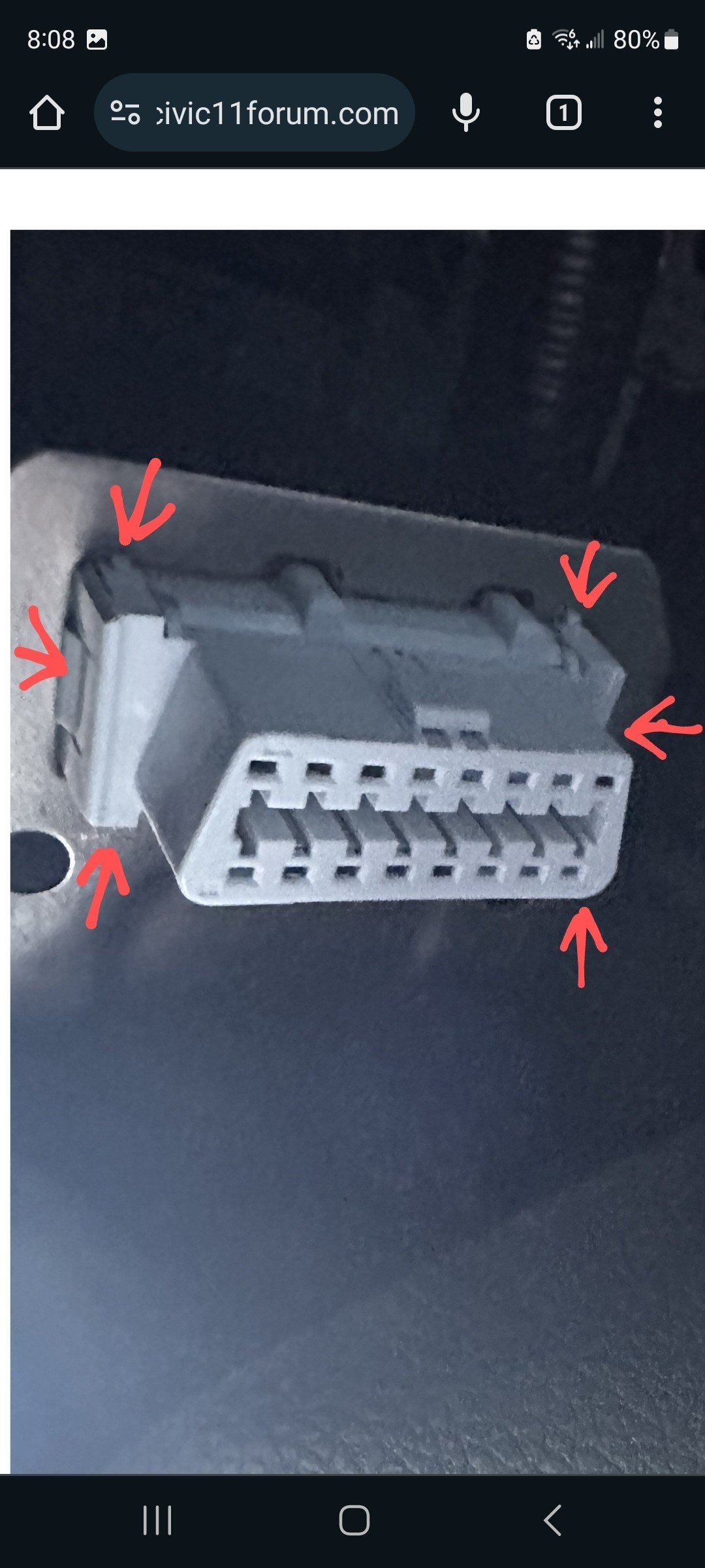
To begin, let’s look at how to detach the OBDII connector from its mounting bracket. As shown in the image above, the connector is secured by retaining clips. These clips are designed to hold the connector firmly in place within the metal bracket. To remove it, you’ll need a small flat-head screwdriver. Gently push each of these retaining clips inwards, one at a time. While doing so, slightly wiggle or angle the connector. Then, push the connector upwards—away from the floorboard—to release it from the bracket. This upward motion is important as it allows the retaining clips to clear the bracket.
Once detached, the back view of the OBDII connector reveals the wiring and pin arrangement. As highlighted in this image, you can see the points where wires connect into the connector. It’s vital to handle this stage carefully to ensure none of the wires or pins are dislodged from their sockets. Keep a hand on the back of the connector during removal to stabilize the wires.
This side view of the OBDII connector illustrates how the metal bracket interfaces with the connector when the retaining clips are engaged. The red line in the image approximates the position of the metal bracket, showing how it securely holds the connector in place under normal conditions.
Here is the bottom view of the OBDII connector, the part you would typically plug your diagnostic tool into. This is the interface that allows communication with your vehicle’s systems for diagnostics and data retrieval.
Focusing on the side of the connector, you’ll notice small teeth with pass-through holes. When the connector is correctly installed in the bracket (represented by the red line), these teeth are compressed. This compression causes nubs to protrude into the pass-through holes, effectively locking each pin into its socket.
Finally, this close-up image shows a pin with a crucial hole. This hole is where the nub from the retaining mechanism sits, preventing the pin from backing out of the connector from the back side. Understanding this mechanism is key if you are inspecting or reassembling the connector.
In conclusion, when working with your OBDII connector, careful observation and gentle handling are paramount. Always ensure you maintain the original orientation and placement of each pin and wire to guarantee proper function of your vehicle’s diagnostic system. This detailed OBDII connector view should provide a solid foundation for understanding and working with this essential automotive component.