1. Understanding OBDII: Your Vehicle’s Diagnostic System
OBDII (On-Board Diagnostics II) is a standardized system implemented in most vehicles since the mid-1990s. It acts as the vehicle’s built-in self-diagnostic system, monitoring various engine and emissions-related parameters. It provides access to a wealth of information crucial for automotive repair and maintenance.
1.1. The Role of OBDII
The OBDII system plays a vital role in:
- Emission Control: Monitoring components related to emissions and ensuring compliance with environmental regulations.
- Fault Detection: Identifying malfunctions in various vehicle systems and storing diagnostic trouble codes (DTCs).
- Data Access: Providing access to real-time data, such as engine speed, coolant temperature, and oxygen sensor readings.
1.2. The Malfunction Indicator Light (MIL)
The malfunction indicator light (MIL), often referred to as the “check engine light,” is a key indicator of OBDII activity. When the OBDII system detects a fault, it illuminates the MIL, alerting the driver to a potential problem.
1.3. Accessing OBDII Data with a Scan Tool
Automotive technicians use OBDII scan tools to access the data stored within the OBDII system. These tools connect to the vehicle’s OBDII port and allow technicians to:
- Read diagnostic trouble codes (DTCs).
- View real-time data streams.
- Clear DTCs after repairs are completed.
Image: An OBDII scan tool connected to a vehicle’s OBDII port, highlighting its role in accessing diagnostic information.
2. Is Your Car OBDII Compliant?
The widespread adoption of OBDII makes it highly likely that your vehicle is compliant. However, it’s essential to confirm, especially for older models.
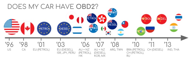
2.1. OBDII Implementation Timeline
- 1996: OBDII mandated in the USA for cars and light trucks.
- 2001: Required in the EU for gasoline cars.
- 2003: Required in the EU for diesel cars (EOBD).
- 2005: OBDII required in the US for medium-duty vehicles.
- 2008: US cars required to use ISO 15765-4 (CAN) as the OBDII basis.
- 2010: OBDII required in US heavy-duty vehicles.
2.2. Identifying OBDII Compliance
Even if your car has a 16-pin OBDII connector, it might not fully support the OBDII protocol. Here’s how to check:
- Production Date: Check the vehicle’s production date. If it falls within the mandated years mentioned above, it’s likely OBDII compliant.
- Vehicle Manual: Consult the vehicle’s owner’s manual. It should explicitly state whether the vehicle supports OBDII.
- OBDII Connector: Visually inspect the OBDII connector. All 16 pins should be present and functional.
3. A Look at the History of OBDII
The development of OBDII was driven by the need for improved emission control and standardized diagnostic procedures.
3.1. The California Influence
The California Air Resources Board (CARB) played a pivotal role in the development of OBDII. In 1991, CARB mandated OBD systems in all new cars sold in California to monitor emissions-related components.
3.2. Standardization Efforts
The Society of Automotive Engineers (SAE) contributed significantly to the standardization of OBDII. SAE developed standards for DTCs and the OBDII connector, ensuring consistency across different manufacturers.
3.3. OBDII’s Evolution
From its initial focus on emissions, OBDII has evolved into a comprehensive diagnostic system. Modern OBDII systems monitor a wide range of vehicle parameters, providing valuable insights into overall vehicle health.
Image: A timeline highlighting key milestones in the history of OBDII.
4. The Future of OBDII: Trends and Innovations
OBDII continues to evolve, with several key trends shaping its future.
4.1. The Rise of OBD3
OBD3 aims to enhance emission control through telematics. This involves equipping vehicles with radio transponders that transmit VIN and DTC information to a central server for monitoring.
4.2. Challenges to Third-Party Data Access
Some manufacturers are exploring ways to restrict third-party access to OBDII data. This could potentially impact the development of aftermarket diagnostic tools and services.
4.3. Alternatives: WWH-OBD and OBDonUDS
These emerging standards seek to improve OBD communication by utilizing the UDS protocol. They offer enhanced data richness and streamlined communication processes.
Image: An illustration of future trends in OBDII, including remote diagnostics and emissions testing.
5. Essential OBDII Standards
OBDII operates on a set of established standards that define its various aspects.
5.1. The OSI Model
The OBDII standards can be visualized using the 7-layer OSI model, which provides a framework for understanding the different communication layers.
5.2. Key Standards Organizations
- SAE: Primarily defines standards for OBDII in the USA.
- ISO: Sets standards for OBDII in Europe and other regions.
5.3. Critical Standards
- SAE J1962 / ISO 15031-3: Specifies the OBDII connector.
- SAE J1979 / ISO 15031-5: Defines the diagnostic services and PIDs.
- ISO 15765-4: Specifies the use of CAN bus for OBDII communication.
Image: An OSI model representation of OBDII and CAN bus, highlighting the relevant standards.
6. The OBDII Connector: Your Access Point
The OBDII connector (SAE J1962 / ISO 15031-3) provides a standardized interface for accessing vehicle data.
6.1. Location
The OBDII connector is typically located near the steering wheel, but it may be hidden behind a panel.
6.2. Pinout
The OBDII connector has 16 pins, each with a specific function. The pinout varies depending on the communication protocol used.
6.3. CAN Bus Connection
In most modern vehicles, pins 6 (CAN-H) and 14 (CAN-L) are connected to the CAN bus, enabling OBDII communication over CAN.
Image: A diagram illustrating the pinout of a typical OBDII connector.
6.4. Type A vs. Type B
OBDII connectors come in two main types:
- Type A: Commonly found in cars and light-duty vehicles (12V power supply).
- Type B: Typically used in medium and heavy-duty vehicles (24V power supply).
Type B connectors have an interrupted groove in the middle, making them incompatible with Type A adapters.
Image: A comparison of Type A and Type B OBDII connectors.
7. OBDII and CAN Bus: A Powerful Combination
CAN bus (Controller Area Network) is the dominant communication protocol used in modern vehicles, and it forms the foundation for OBDII communication.
7.1. ISO 15765-4 (Diagnostics over CAN)
ISO 15765-4 defines the specific requirements for using CAN bus for OBDII communication. It specifies:
- CAN bus bit-rate (250K or 500K).
- CAN ID format (11-bit or 29-bit).
- CAN IDs used for OBDII requests and responses.
- Data length (8 bytes per CAN frame).
- Maximum OBDII adapter cable length (5 meters).
7.2. CAN Identifiers
OBDII communication involves request and response messages.
- 11-bit CAN IDs: The Functional Addressing ID (0x7DF) is used to request data from all OBDII-compliant ECUs. The response IDs (0x7E8-0x7EF) indicate the ECU that is responding.
- 29-bit CAN IDs: Used in some vehicles, particularly vans and heavy-duty vehicles. The Functional Addressing CAN ID is 0x18DB33F1.
7.3. OBDII vs. Proprietary CAN Protocols
It’s important to understand that vehicle ECUs do not rely solely on OBDII to function. Manufacturers implement their own proprietary CAN protocols for internal communication. OBDII exists as an additional layer on top of these proprietary protocols.
When connecting a CAN bus data logger to the OBDII connector, you may see OEM-specific CAN data alongside the OBDII data. In newer vehicles, a gateway might restrict access to the OEM-specific CAN data.
7.4. Bit-Rate and ID Validation
OBDII may use either 250K or 500K bit-rates and 11-bit or 29-bit CAN IDs. It’s crucial to determine the correct combination for your vehicle. ISO 15765-4 provides a systematic initialization sequence for this purpose.
Image: A flowchart illustrating the process of validating the OBDII bit-rate and CAN ID.
7.5. Five Lower-Layer Protocols
While CAN bus is the dominant protocol, older vehicles may use one of the following:
- ISO 14230-4 (KWP2000)
- ISO 9141-2
- SAE J1850 (VPW)
- SAE J1850 (PWM)
Image: A visual representation of the five lower-layer protocols used in OBDII.
8. Transporting OBDII Messages via ISO-TP
ISO-TP (ISO 15765-2) is a transport protocol used to communicate OBDII data over CAN. It allows for the transmission of payloads larger than 8 bytes, which is necessary for data such as the VIN and DTCs.
8.1. Segmentation, Flow Control, and Reassembly
ISO-TP handles the segmentation of large messages into smaller CAN frames, flow control to manage the transmission process, and reassembly of the messages at the receiving end.
8.2. Single Frame (SF) Communication
When the OBDII data fits within a single CAN frame, ISO-TP uses a “Single Frame” format. The first byte of the data field indicates the payload length, leaving 7 bytes for OBDII data.
Image: A diagram illustrating the different frame types used in ISO-TP communication.
9. Understanding the OBDII Diagnostic Message
The OBDII diagnostic message (SAE J1979, ISO 15031-5) is the core of the OBDII communication process.
9.1. Message Structure
An OBDII message consists of:
- Identifier (CAN ID)
- Data Length (PCI field)
- Data:
- Mode (Service)
- Parameter ID (PID)
- Data Bytes
9.2. Example: Requesting Vehicle Speed
To request vehicle speed, an external tool sends a request message with CAN ID 0x7DF, Mode 0x01, and PID 0x0D. The vehicle responds with CAN ID 0x7E8 and the vehicle speed data.
9.3. OBDII Services (Modes)
OBDII defines 10 diagnostic services, or modes. These modes allow you to access different types of data, such as real-time data, DTCs, and freeze-frame data.
- Mode 0x01: Show current real-time data.
- Mode 0x03: Show stored Diagnostic Trouble Codes (DTCs).
- Mode 0x04: Clear Diagnostic Trouble Codes (DTCs).
Image: A list of the 10 OBDII diagnostic services (modes).
9.4. OBDII Parameter IDs (PIDs)
Each OBDII mode contains parameter IDs (PIDs). PIDs are used to identify specific data parameters within a given mode.
- Mode 0x01: Contains approximately 200 standardized PIDs for real-time data.
- PID 0x00 (Mode 0x01): A mandatory PID that indicates which PIDs are supported by the ECU.
Image: A visual representation of an OBDII request and response message, highlighting the mode and PID fields.
9.5. Tip: Using an OBDII PID Overview Tool
SAE J1979 and ISO 15031-5 provide scaling information for standard OBDII PIDs, allowing you to convert the raw data into physical values. Several online tools can help you look up PIDs and decode the data.
10. Logging and Decoding OBDII Data: A Practical Guide
Here’s a practical example of how to log and decode OBDII data using a CAN bus data logger like the CANedge. The CANedge allows you to configure custom CAN frames for transmitting OBDII requests and logging the responses.
10.1. Step 1: Test Bit-Rate, IDs, and Supported PIDs
Before logging data, you need to determine the correct bit-rate, CAN IDs, and supported PIDs for your vehicle.
- Send a CAN frame at 500K and check if successful (if not, try 250K).
- Use the identified bit-rate for subsequent communication.
- Send multiple “Supported PIDs” requests and review the responses.
- Based on response IDs, determine whether 11-bit or 29-bit CAN IDs are used.
- Based on response data, identify the supported PIDs.
10.2. Step 2: Configure OBDII PID Requests
Configure your transmit list with the PIDs you want to log.
- CAN IDs: Use “Physical Addressing” request IDs (e.g., 0x7E0) to avoid multiple responses to each request.
- Spacing: Add 300-500 ms between each OBDII request to prevent overloading the ECUs.
- Battery Drain: Use triggers to stop transmitting when the vehicle is inactive.
- Filters: Add filters to only record OBDII responses.
10.3. Step 3: DBC Decode Raw OBDII Data
To analyze and visualize your data, you need to decode the raw OBDII data into physical values.
Use an OBDII DBC file to decode the data in a CAN bus software tool. Remember that decoding OBDII data is more complex than decoding regular CAN signals because different OBDII PIDs are transported using the same CAN ID. You need to leverage the CAN ID, OBDII mode, and OBDII PID to identify the signal. This is known as “extended multiplexing.”
Image: A diagram illustrating the setup for logging OBDII data with a CAN bus data logger.
11. OBDII Multi-Frame Examples
ISO-TP is used to handle multi-frame communication in OBDII.
11.1. Example 1: Requesting the VIN
To extract the Vehicle Identification Number (VIN), use mode 0x09 and PID 0x02. The tester tool sends a Single Frame request, and the vehicle responds with a multi-frame response containing the VIN.
11.2. Example 2: OBDII Multi-PID Request (6x)
You can request up to 6 mode 0x01 OBDII PIDs in a single request frame. The ECU will respond with data for supported PIDs, potentially across multiple frames. However, this approach can be complex to decode.
11.3. Example 3: Diagnostic Trouble Codes (DTCs)
You can use OBDII to request emissions-related DTCs using mode 0x03. The ECU will respond with the number of DTCs stored, with each DTC taking up 2 data bytes.
12. OBDII Data Logging: Use Case Examples
OBDII data logging has numerous applications in the automotive industry.
12.1. Logging Data from Cars
OBDII data can be used to reduce fuel costs, improve driving habits, test prototype parts, and analyze insurance claims.
12.2. Real-Time Car Diagnostics
OBDII interfaces can stream human-readable data in real-time, enabling technicians to diagnose vehicle issues efficiently.
12.3. Predictive Maintenance
OBDII loggers can be used to monitor vehicles remotely and predict potential breakdowns.
12.4. Vehicle Blackbox Logger
An OBDII logger can serve as a “blackbox” for vehicles, providing data for accident investigations and diagnostics.
Image: Various use cases for OBDII data logging.
Do you have an OBDII data logging use case? Contact CARDIAGTECH.NET for expert guidance!
Unlock the Power of OBDII & CAN Protocol with CARDIAGTECH.NET
Ready to take your automotive diagnostics to the next level? CARDIAGTECH.NET offers a wide range of OBDII scan tools and data loggers to meet your needs.
Benefits of Choosing CARDIAGTECH.NET
- Expert Guidance: Our team of automotive professionals can help you select the right tools for your specific requirements.
- High-Quality Products: We offer only the highest-quality OBDII scan tools and data loggers from trusted manufacturers.
- Competitive Pricing: We provide competitive pricing to ensure you get the best value for your investment.
- Exceptional Customer Support: Our dedicated customer support team is available to assist you with any questions or issues.
Ready to Get Started?
-
Explore our selection of OBDII scan tools and data loggers: CARDIAGTECH.NET
-
Contact us for a free consultation:
- Address: 276 Reock St, City of Orange, NJ 07050, United States
- WhatsApp: +1 (641) 206-8880
- Website: CARDIAGTECH.NET
Let CARDIAGTECH.NET be your partner in unlocking the power of OBDII & CAN Protocol for efficient and effective automotive diagnostics and repair!
Frequently Asked Questions (FAQs)
1. What is the OBDII protocol?
OBDII (On-Board Diagnostics II) is a standardized system that allows you to access diagnostic information from a vehicle’s engine and other systems.
2. How can I tell if my car is OBDII compliant?
Check the vehicle’s production date, consult the owner’s manual, or inspect the OBDII connector.
3. What is the CAN bus?
CAN (Controller Area Network) bus is a communication protocol used in vehicles to allow different electronic control units (ECUs) to communicate with each other.
4. What is the OBDII connector used for?
The OBDII connector allows you to connect a scan tool or data logger to the vehicle’s OBDII system to access diagnostic data.
5. What are DTCs?
DTCs (Diagnostic Trouble Codes) are codes stored by the OBDII system when it detects a fault. These codes help technicians diagnose the cause of the problem.
6. What is a scan tool?
A scan tool is a device used to connect to a vehicle’s OBDII system and read diagnostic data, including DTCs and real-time data streams.
7. What is a PID?
PID (Parameter ID) is a code that identifies a specific data parameter within the OBDII system, such as engine speed or coolant temperature.
8. What is ISO 15765-4?
ISO 15765-4 specifies the requirements for using CAN bus for OBDII communication.
9. How do I decode OBDII data?
You can decode OBDII data using an OBDII DBC file and a CAN bus software tool.
10. What are some use cases for OBDII data logging?
OBDII data logging can be used for various applications, including reducing fuel costs, improving driving habits, predictive maintenance, and vehicle blackbox logging.
By providing this in-depth guide, CARDIAGTECH.NET aims to empower automotive professionals with the knowledge and tools they need to excel in their field. Remember to contact us with any questions or for assistance in choosing the right OBDII solutions for your business.