
The Obdii Can Bus High And Low Specs are crucial for automotive diagnostics and repair. CARDIAGTECH.NET helps you delve into the intricacies of this communication protocol, offering expertise and tools to enhance your diagnostic capabilities. By understanding the CAN bus specifications, technicians can accurately diagnose and resolve issues, leading to improved vehicle performance and customer satisfaction. Explore the world of automotive diagnostics with CARDIAGTECH.NET and unlock the potential of vehicle communication systems through CAN bus troubleshooting, data interpretation and network analysis.
1. What is the OBDII CAN Bus High and Low?
The On-Board Diagnostics II (OBDII) Controller Area Network (CAN) bus is a communication standard used in vehicles. It allows various electronic control units (ECUs) to communicate with each other without needing a central computer. This system is vital for modern automotive diagnostics, enabling technicians to access and interpret data from different parts of the vehicle. Think of the CAN bus as the nervous system of a car, where each ECU is a vital organ exchanging data smoothly.
1.1 Understanding CAN Bus Components
To fully grasp the OBDII CAN bus, it’s essential to understand its core components. The bus consists of two wires, CAN High (CAN_H) and CAN Low (CAN_L), which form a twisted pair. This physical setup ensures effective and reliable data transmission.
- CAN High (CAN_H): Carries the dominant signal in the differential pair.
- CAN Low (CAN_L): Carries the recessive signal in the differential pair.
- ECUs (Electronic Control Units): These are the nodes on the CAN bus network, each responsible for controlling specific vehicle functions.
1.2 Key Specs and Voltage Levels
Understanding the voltage specifications of the CAN bus is fundamental for diagnostics. The CAN High and CAN Low wires operate with specific voltage levels that indicate the state of the bus.
| State | CAN High (V) | CAN Low (V) | Differential Voltage (V) |
|---|---|---|---|
| Recessive (Idle) | 2.5 | 2.5 | 0 |
| Dominant (Active) | 3.5 | 1.5 | 2.0 |

These voltage levels are essential for interpreting the signals on the CAN bus. A dominant state signifies that a node is actively transmitting data, while a recessive state indicates the bus is idle.
1.3 Why These Specs Matter
Adhering to the correct voltage specifications is crucial for maintaining the integrity of the CAN bus communication. Deviations from these levels can indicate potential issues such as wiring problems, faulty ECUs, or termination resistor failures. Accurate voltage readings help technicians pinpoint the source of problems, ensuring effective repairs and vehicle performance.
2. Identifying Key CAN Bus Variants
Before diving deeper, it’s important to recognize that there are several CAN bus variants, each designed for specific applications and performance requirements.
2.1 High-Speed CAN
Also known as Classical CAN, this is the most common type found in automotive applications. It supports data rates up to 1 Mbit/s and is used for critical systems like engine management and braking. High-Speed CAN is characterized by its robustness and efficiency in transmitting data quickly across the vehicle’s network.
2.2 Low-Speed CAN
Also known as Fault-Tolerant CAN, this variant is designed to maintain communication even when one of the wires is damaged. It typically operates at lower data rates (up to 125 kbit/s) and is used for less critical systems where reliability is more important than speed. However, it is increasingly being replaced by LIN bus for cost-effectiveness.
2.3 CAN FD (Flexible Data-Rate)
This is an enhanced version of CAN that supports higher data rates and larger payloads. CAN FD can reach speeds of up to 8 Mbit/s, making it suitable for advanced applications like ADAS (Advanced Driver Assistance Systems). While adoption is growing, it has not yet fully replaced Classical CAN.
2.4 CAN XL
The latest advancement in CAN technology, CAN XL, offers even higher data rates and longer payloads, bridging the gap between CAN and Automotive Ethernet. It is designed for future automotive architectures requiring extensive data exchange. However, as of 2024, CAN XL is still in the early stages of deployment.
2.5 Practical Implications
Understanding these variants is crucial because each has different physical and data link layer specifications. Using the wrong diagnostic tools or settings for a specific CAN variant can lead to inaccurate readings and misdiagnosis.
3. Benefits of Using CAN Bus
The CAN bus system offers several key advantages that make it a fundamental part of modern vehicles.
3.1 Reduced Wiring Complexity
Traditional wiring systems require dedicated wires between each component, leading to complex and heavy wiring harnesses. CAN bus simplifies this by allowing multiple ECUs to communicate over a single pair of wires. This reduces the amount of wiring needed, saving weight and costs. According to connector supplier.com, switching to CAN bus can reduce a vehicle’s wiring harness weight by up to 20 kg, thereby reducing fuel consumption.
3.2 Cost-Effective Solution
By reducing wiring and component costs, CAN bus offers a more economical solution for vehicle communication. The widespread adoption of CAN has also led to lower prices for controllers, transceivers, and diagnostic tools.
3.3 Centralized Diagnostics
CAN bus provides a single point of entry for accessing data from all ECUs in the network. This simplifies diagnostics, allowing technicians to quickly identify and address issues without needing to access each component individually. Centralized diagnostics save time and improve the accuracy of fault detection.
3.4 Robust Communication
CAN bus is designed to be robust against electrical disturbances and electromagnetic interference (EMI). Differential signaling and error-handling mechanisms ensure data integrity even in harsh operating environments. The CAN bus system includes error detection mechanisms, such as bit errors, stuff errors, CRC errors, form errors, and ACK errors, as detailed in our guide to CAN bus errors.
3.5 Efficient Data Transmission
CAN frames are prioritized by ID, ensuring that critical data gets immediate access to the bus. This arbitration mechanism prevents data collisions and ensures efficient utilization of the bus bandwidth. The CAN bus ensures the highest priority messages are transmitted without interruption, optimizing real-time performance.
4. CAN Bus Protocol: The Technical Details
To effectively troubleshoot and diagnose issues related to the CAN bus, a thorough understanding of its technical aspects is necessary.
4.1 Physical Layer
The physical layer defines the hardware requirements for CAN bus communication. It includes specifications for cable types, voltage levels, impedance, and termination. According to ISO 11898-2, the physical layer must meet these criteria to ensure reliable data transmission.
- Cable Type: Typically, a twisted pair cable is used to minimize interference.
- Baud Rate: High-speed CAN supports baud rates up to 1 Mbit/s, while other variants may have lower rates.
- Termination: A 120 Ohm resistor is required at each end of the bus to prevent signal reflections.
4.2 Data Link Layer
The data link layer defines the rules for transmitting data over the CAN bus. It includes specifications for frame formats, error handling, and arbitration. As defined in ISO 11898-1, the data link layer ensures data integrity and manages bus access.
- Frame Formats: CAN uses several frame types, including data frames, remote frames, error frames, and overload frames.
- Error Handling: Mechanisms such as CRC (Cyclic Redundancy Check) are used to detect and handle errors.
- Arbitration: A bitwise arbitration process ensures that the highest priority message is transmitted first.
4.3 Understanding CAN Frames
Communication on the CAN bus is done through CAN frames. A standard CAN data frame includes several fields:
- Start of Frame (SOF): Indicates the beginning of the frame.
- Identifier (ID): Specifies the message priority and source.
- Remote Transmission Request (RTR): Indicates whether data is being sent or requested.
- Control Field: Contains information about the data length.
- Data Field: Contains the actual data being transmitted.
- Cyclic Redundancy Check (CRC): Ensures data integrity.
- Acknowledge (ACK): Confirms successful reception of the frame.
- End of Frame (EOF): Marks the end of the frame.
4.4 Practical Significance
Understanding these low-level details is critical for diagnosing CAN bus issues. By analyzing the frame data, technicians can identify communication errors, data corruption, and other problems that affect vehicle performance.
5. Higher-Layer Protocols
While the CAN bus provides the basic communication framework, higher-layer protocols define how data is interpreted and used. These protocols add additional layers of functionality on top of the CAN bus, providing standardized methods for various applications.
5.1 Common Protocols
- OBD-II: Used for vehicle diagnostics, providing access to emission-related data and diagnostic trouble codes (DTCs).
- SAE J1939: Used in heavy-duty vehicles for communication between components such as engines, transmissions, and braking systems.
- CANopen: Used in industrial automation for communication between devices in a network.
- NMEA 2000: Used in marine electronics for connecting sensors and displays.
- UDS (Unified Diagnostic Services): Used for advanced diagnostics and ECU reprogramming.
5.2 How They Work
Higher-layer protocols define the format and meaning of data transmitted over the CAN bus. They specify how to encode and decode messages, handle errors, and manage communication between devices. This standardization allows different devices to communicate seamlessly, regardless of the manufacturer.
5.3 Real-World Analogy
Think of CAN bus as the basic infrastructure, like roads, while higher-layer protocols are the traffic rules and signs that govern how vehicles (data) move on those roads. Without these rules, there would be chaos and no meaningful communication.
5.4 Practical Examples
- OBD-II: When a technician connects an OBD-II scanner to a vehicle, the scanner uses the OBD-II protocol to request diagnostic information from the ECU.
- SAE J1939: In a truck, the engine control module (ECM) uses J1939 to send data about engine speed and temperature to the instrument cluster.
- CANopen: In a factory automation system, CANopen is used to control motors, sensors, and other devices, allowing them to work together seamlessly.
Understanding these protocols is essential for interpreting CAN bus data and diagnosing vehicle issues effectively.
6. Diagnosing OBDII CAN Bus Issues
Diagnosing issues with the OBDII CAN bus requires a systematic approach. Here are some common problems and methods to troubleshoot them.
6.1 Common Problems
- No Communication: The diagnostic tool cannot establish communication with the vehicle’s ECUs.
- Intermittent Communication: Communication is inconsistent or drops out.
- Data Errors: Incorrect or corrupted data is displayed.
- Specific DTCs: Diagnostic Trouble Codes indicate CAN bus related issues.
6.2 Troubleshooting Steps
- Visual Inspection: Check the wiring and connectors for damage, corrosion, or loose connections.
- Voltage Checks: Verify the voltage levels on the CAN High and CAN Low wires.
- Continuity Tests: Ensure there are no breaks or shorts in the wiring.
- Termination Resistor Check: Verify the presence and correct resistance (120 Ohms) of the termination resistors.
- Oscilloscope Analysis: Use an oscilloscope to analyze the CAN bus waveforms for signal integrity.
6.3 Tools and Equipment
- Multimeter: For measuring voltage, resistance, and continuity.
- Oscilloscope: For analyzing signal waveforms.
- Diagnostic Scanner: For reading DTCs and accessing live data.
- CAN Bus Analyzer: For advanced diagnostics and protocol analysis.
6.4 Practical Tips
- Start with the Basics: Always begin with a visual inspection and basic voltage checks.
- Use a Known Good Tool: Ensure your diagnostic tools are functioning correctly.
- Check for Updates: Keep your diagnostic software up to date.
- Consult Vehicle-Specific Information: Refer to the vehicle’s service manual for specific troubleshooting procedures and wiring diagrams.
6.5 Step-by-Step Example
- Problem: No communication with the ECU.
- Visual Inspection: Check the OBDII connector and wiring for damage.
- Voltage Check: Measure the voltage on CAN High and CAN Low.
- CAN High should be around 2.5V in the recessive state and 3.5V in the dominant state.
- CAN Low should be around 2.5V in the recessive state and 1.5V in the dominant state.
- Termination Resistor Check: Measure the resistance between CAN High and CAN Low with the ignition off. It should be approximately 60 Ohms (two 120 Ohm resistors in parallel).
- If the voltage levels are incorrect: Investigate wiring issues, faulty ECUs, or termination resistor problems.
- If the resistance is incorrect: Check the termination resistors at each end of the bus.
By following these steps, you can systematically diagnose and resolve CAN bus issues, ensuring reliable vehicle communication and performance.
7. The Role of Termination Resistors
Termination resistors are essential components in the CAN bus system. They play a crucial role in maintaining signal integrity and preventing communication errors.
7.1 What They Do
Termination resistors are placed at each end of the CAN bus to match the impedance of the cable. This prevents signal reflections, which can cause interference and data corruption. The standard resistance value for termination resistors in a CAN bus system is 120 Ohms.
7.2 Why They Are Important
- Prevent Signal Reflections: Without termination resistors, signals can bounce back and forth on the bus, causing interference.
- Maintain Signal Integrity: Proper termination ensures that the signals are clean and clear, reducing the risk of errors.
- Ensure Reliable Communication: By preventing interference and maintaining signal integrity, termination resistors help ensure reliable communication between ECUs.
7.3 How to Check Them
You can check the termination resistors using a multimeter. Here’s how:
- Turn off the Ignition: Ensure the vehicle’s ignition is turned off to prevent any electrical interference.
- Locate the CAN Bus Wires: Find the CAN High and CAN Low wires, typically at the OBDII connector or at an ECU.
- Measure Resistance: Use a multimeter to measure the resistance between the CAN High and CAN Low wires.
- Verify the Value: The resistance should be approximately 60 Ohms. This is because there are two 120 Ohm resistors in parallel.
7.4 Common Issues
- Missing Resistors: If one or both termination resistors are missing, the resistance will be significantly higher (or infinite).
- Incorrect Resistance: If the resistors have drifted out of specification, the resistance will be different from 60 Ohms.
- Damaged Resistors: Physical damage to the resistors can also affect their performance.
7.5 Practical Implications
If the termination resistors are not functioning correctly, you may experience communication errors, intermittent connectivity, or a complete loss of communication on the CAN bus. Addressing termination resistor issues is often a critical step in troubleshooting CAN bus problems.
8. Contactless CAN Bus Readers
Contactless CAN bus readers provide a non-invasive way to access CAN bus data. These devices use induction to read signals from the CAN High and CAN Low wires without physically connecting to them.
8.1 How They Work
Contactless readers clamp around the CAN bus wires and detect the electromagnetic field generated by the signals. This allows them to read the data being transmitted without disrupting the communication.
8.2 Advantages
- Non-Invasive: No need to cut or splice wires, reducing the risk of damage.
- Easy Installation: Simple to install and remove, making them ideal for temporary monitoring.
- Versatile: Can be used in a variety of applications, including automotive, industrial, and marine.
8.3 Disadvantages
- Read-Only: Contactless readers can only read data; they cannot transmit messages onto the CAN bus.
- Power Requirement: Typically require an external power source.
- Signal Sensitivity: May be affected by strong electromagnetic interference.
8.4 Use Cases
- Data Logging: Recording CAN bus data for analysis and troubleshooting.
- Reverse Engineering: Analyzing CAN bus traffic to understand proprietary protocols.
- Fleet Management: Monitoring vehicle performance and driver behavior.
- Warranty Protection: Avoids altering the vehicle’s wiring, preserving the warranty.
8.5 Practical Considerations
When using a contactless CAN bus reader, ensure that it is properly aligned with the CAN bus wires and that it is not affected by external interference. Also, keep in mind that you will need a separate power source for the reader.
8.6 Example Scenario
Suppose you want to monitor the CAN bus data on a vehicle without affecting its warranty. A contactless CAN bus reader allows you to capture the data without cutting or splicing any wires. You simply clamp the reader around the CAN High and CAN Low wires, connect it to a power source, and start logging data.
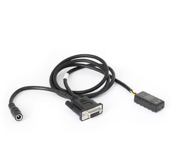
9. Connecting to the CAN Bus: Adapters and Cables
Connecting to the CAN bus requires the right adapters and cables. The choice depends on the application and the type of connector available.
9.1 Common Adapters
- OBDII Adapter: Used for connecting to the OBDII port in cars and light trucks.
- J1939 Adapter: Used for connecting to the J1939 diagnostic port in heavy-duty vehicles.
- M12 Adapter: Used for connecting to CAN bus networks in industrial and marine applications.
- DB9 Adapter: A generic adapter with a DB9 connector for custom connections.
9.2 OBDII Adapter
The OBDII adapter is the most common type used in automotive diagnostics. It connects to the 16-pin OBDII port found in most vehicles manufactured after 1996.
- Pinout: The OBDII port has specific pins for CAN High and CAN Low, as well as power and ground.
- Functionality: Allows access to emission-related data, diagnostic trouble codes (DTCs), and live data.
- Use Cases: Vehicle diagnostics, performance monitoring, and data logging.
9.3 J1939 Adapter
The J1939 adapter is used in heavy-duty vehicles such as trucks, buses, and construction equipment. It connects to the 9-pin J1939 diagnostic port.
- Pinout: The J1939 port has specific pins for CAN High, CAN Low, power, and ground.
- Functionality: Allows access to data related to engine, transmission, braking system, and other vehicle components.
- Use Cases: Fleet management, performance monitoring, and diagnostics.
9.4 M12 Adapter
The M12 adapter is used in industrial and marine applications. It features a robust, waterproof connector that is suitable for harsh environments.
- Pinout: The M12 connector has specific pins for CAN High, CAN Low, power, and ground.
- Functionality: Allows access to CAN bus data in industrial and marine systems.
- Use Cases: Industrial automation, marine electronics, and data logging.
9.5 Practical Considerations
When selecting an adapter, ensure that it is compatible with the type of connector on the vehicle or equipment you are working with. Also, check the pinout to ensure that the CAN High and CAN Low wires are correctly connected.
9.6 Example Scenario
Suppose you are working on a heavy-duty truck and need to access the CAN bus data. You would use a J1939 adapter to connect to the 9-pin diagnostic port. This allows you to read data related to the engine, transmission, and other vehicle systems.
10. Logging and Decoding CAN Bus Data
Logging and decoding CAN bus data is essential for understanding and troubleshooting vehicle systems. This process involves capturing raw CAN bus data and converting it into human-readable values.
10.1 Data Logging
Data logging involves capturing CAN bus traffic over a period of time. This can be done using a CAN bus logger, which is a device that records CAN bus data and stores it for later analysis.
- CAN Bus Logger: A device that captures and stores CAN bus data.
- Data Storage: CAN bus loggers typically store data on an SD card or internal memory.
- Time Synchronization: Accurate time synchronization is essential for correlating data from multiple sources.
10.2 Data Decoding
Data decoding involves converting raw CAN bus data into human-readable values. This requires a CAN database (DBC) file, which contains information about the CAN bus messages and signals.
- DBC File: A text file that contains information about CAN bus messages and signals.
- Decoding Software: Software that uses the DBC file to convert raw CAN bus data into human-readable values.
- Signal Scaling: The process of converting raw data values into physical units, such as RPM, temperature, or pressure.
10.3 Step-by-Step Process
- Connect the CAN Bus Logger: Connect the CAN bus logger to the vehicle’s diagnostic port using the appropriate adapter.
- Configure the Logger: Configure the CAN bus logger to capture the desired data.
- Start Logging: Start logging data and drive the vehicle or operate the equipment.
- Stop Logging: Stop logging data when you have captured enough information.
- Download the Data: Download the data from the CAN bus logger to your computer.
- Load the DBC File: Load the DBC file into your decoding software.
- Decode the Data: Use the decoding software to convert the raw CAN bus data into human-readable values.
- Analyze the Data: Analyze the decoded data to identify any issues or anomalies.
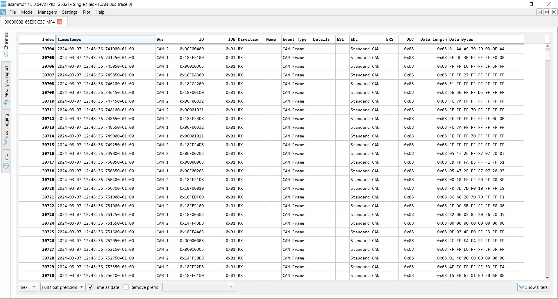
10.4 Practical Tools
- asammdf: A popular tool for viewing and analyzing CAN bus data.
- CANalyzer: A professional tool for CAN bus analysis and simulation.
- Vector Informatik Tools: A range of tools for CAN bus development and testing.
10.5 Example Scenario
Suppose you are troubleshooting an engine performance issue. You can use a CAN bus logger to capture data related to engine speed, throttle position, and fuel injection. By decoding this data, you can identify any anomalies that may be causing the performance issue.
10.6 Importance of Accurate Data
Accurate data logging and decoding are essential for effective troubleshooting and diagnostics. Ensure that you are using the correct DBC file and that your decoding software is properly configured.
11. Staying Compliant and Safe
Working with the OBDII CAN bus system requires adherence to safety standards and best practices. This ensures the safety of both the technician and the vehicle.
11.1 Safety Precautions
- Disconnect the Battery: Before working on the CAN bus system, disconnect the vehicle’s battery to prevent electrical shocks.
- Use Proper Tools: Use insulated tools to prevent shorts and electrical hazards.
- Follow Service Manuals: Always follow the vehicle manufacturer’s service manuals for specific procedures and safety information.
- Wear Safety Gear: Wear appropriate safety gear, such as gloves and eye protection.
11.2 Best Practices
- Keep Diagnostic Tools Updated: Regularly update your diagnostic tools with the latest software and firmware.
- Use High-Quality Components: Use high-quality adapters, cables, and connectors to ensure reliable connections.
- Verify Connections: Double-check all connections before powering up the system.
- Document Your Work: Keep detailed records of your diagnostic procedures and findings.
11.3 Compliance Standards
- ISO 11898: The international standard for CAN bus communication.
- SAE J1939: The standard for CAN bus communication in heavy-duty vehicles.
- OBDII Regulations: Regulations governing the use of OBDII for vehicle diagnostics.
11.4 Avoiding Common Mistakes
- Incorrect Wiring: Double-check the wiring connections to avoid shorts and damage to the ECUs.
- Using the Wrong Adapter: Ensure that you are using the correct adapter for the vehicle or equipment you are working with.
- Ignoring DTCs: Pay attention to diagnostic trouble codes (DTCs) and follow the recommended troubleshooting procedures.
- Overlooking Physical Damage: Inspect the wiring and connectors for physical damage, such as corrosion or breaks.
11.5 Staying Informed
- Training Courses: Attend training courses to stay up-to-date on the latest CAN bus technologies and diagnostic techniques.
- Industry Forums: Participate in industry forums and online communities to share knowledge and learn from others.
- Technical Publications: Read technical publications and service bulletins to stay informed about new developments and best practices.
11.6 Importance of Compliance
Compliance with safety standards and best practices is essential for ensuring the reliability and safety of the CAN bus system. Failure to comply can result in damage to the vehicle, injury to the technician, and legal liabilities.
12. Purchasing Tools from CARDIAGTECH.NET
When it comes to acquiring the necessary tools for diagnosing and repairing OBDII CAN bus systems, CARDIAGTECH.NET stands out as a reliable and comprehensive provider.
12.1 Why Choose CARDIAGTECH.NET?
CARDIAGTECH.NET offers a wide range of high-quality diagnostic tools and equipment specifically designed for automotive technicians. Here are some reasons to choose CARDIAGTECH.NET:
- Extensive Selection: CARDIAGTECH.NET offers a diverse selection of tools, including multimeters, oscilloscopes, diagnostic scanners, and CAN bus analyzers.
- High-Quality Products: CARDIAGTECH.NET only offers products from reputable manufacturers, ensuring that you are getting high-quality, reliable tools.
- Expert Support: CARDIAGTECH.NET provides expert technical support to help you choose the right tools and troubleshoot any issues you may encounter.
- Competitive Prices: CARDIAGTECH.NET offers competitive prices on all of its products, making it an affordable option for automotive technicians.
- Convenient Online Ordering: CARDIAGTECH.NET offers a convenient online ordering process, allowing you to purchase tools from the comfort of your own home or shop.
12.2 Featured Products
Here are some featured products available from CARDIAGTECH.NET that are essential for working with OBDII CAN bus systems:
- Multimeters: Used for measuring voltage, resistance, and continuity.
- Oscilloscopes: Used for analyzing signal waveforms and identifying communication errors.
- Diagnostic Scanners: Used for reading diagnostic trouble codes (DTCs) and accessing live data.
- CAN Bus Analyzers: Used for advanced diagnostics and protocol analysis.
- Adapters and Cables: Used for connecting to the vehicle’s diagnostic port.
12.3 How to Purchase
Purchasing tools from CARDIAGTECH.NET is easy. Simply visit the website, browse the product catalog, and add the desired items to your cart. Then, proceed to checkout and follow the instructions to complete your purchase.
12.4 Contact Information
If you have any questions or need assistance, you can contact CARDIAGTECH.NET using the following information:
- Address: 276 Reock St, City of Orange, NJ 07050, United States
- WhatsApp: +1 (641) 206-8880
- Website: CARDIAGTECH.NET
12.5 Call to Action
Don’t wait any longer to get the tools you need for diagnosing and repairing OBDII CAN bus systems. Contact CARDIAGTECH.NET today and start improving your diagnostic capabilities.
- Visit the website: CARDIAGTECH.NET
- Contact via WhatsApp: +1 (641) 206-8880
By purchasing tools from CARDIAGTECH.NET, you can ensure that you have the right equipment for the job and that you are providing your customers with the best possible service.
FAQ Section: OBDII CAN Bus High and Low
Here are some frequently asked questions about OBDII CAN Bus High and Low:
1. What is the CAN bus?
The CAN bus (Controller Area Network) is a communication system used in vehicles to allow ECUs (Electronic Control Units) to communicate with each other without a host computer.
2. What are CAN High and CAN Low?
CAN High (CAN_H) and CAN Low (CAN_L) are the two wires that make up the physical CAN bus. They form a twisted pair that carries differential signals for communication between ECUs.
3. What are the typical voltage levels for CAN High and CAN Low?
In the recessive state, both CAN High and CAN Low are around 2.5V. In the dominant state, CAN High is around 3.5V, and CAN Low is around 1.5V.
4. Why are termination resistors important in a CAN bus system?
Termination resistors are used to prevent signal reflections and maintain signal integrity. They are typically 120 Ohms and are placed at each end of the CAN bus.
5. What is a DBC file?
A DBC (CAN database) file is a text file that contains information about the CAN bus messages and signals. It is used to decode raw CAN bus data into human-readable values.
6. What is OBDII?
OBDII (On-Board Diagnostics II) is a standardized system used in vehicles for diagnostics. It provides access to emission-related data and diagnostic trouble codes (DTCs).
7. What tools are needed for diagnosing CAN bus issues?
Common tools include multimeters, oscilloscopes, diagnostic scanners, and CAN bus analyzers.
8. What is a contactless CAN bus reader?
A contactless CAN bus reader is a device that reads CAN bus data without physically connecting to the wires. It uses induction to detect the signals.
9. How do I check the termination resistors in a CAN bus system?
You can check the termination resistors using a multimeter. Measure the resistance between CAN High and CAN Low with the ignition off. The resistance should be approximately 60 Ohms.
10. What is J1939?
J1939 is a standard for CAN bus communication in heavy-duty vehicles. It defines the format and meaning of data transmitted between components such as engines, transmissions, and braking systems.
By addressing these common questions, you can gain a better understanding of the OBDII CAN bus system and how to troubleshoot related issues effectively.