As a car repair expert at autelfrance.com, I’m excited to share a detailed breakdown of a recent project focused on creating a custom OBDII Bluetooth adapter. This project not only enhances vehicle diagnostics but also incorporates a valuable feature: data logging to a memory card. This DIY approach provides an insightful look into vehicle data and offers a cost-effective alternative to off-the-shelf solutions.
This journey involved overcoming several hurdles, both in hardware and software, but the result is a functional OBDII Bluetooth adapter built around the Arduino Nano platform. Let’s delve into the components and steps involved in bringing this project to life.
Hardware Components
The foundation of this OBDII Bluetooth adapter lies in a few key hardware components, readily available and relatively inexpensive:
- Arduino Nano: This microcontroller serves as the brains of the adapter, processing data and managing communication. Its compact size and capabilities make it ideal for this project.
- HC-06 Bluetooth Module: Enables wireless communication, allowing the adapter to transmit data to devices like smartphones or laptops. This module uses Bluetooth Classic for reliable data transfer.
- L9637D Transceiver: This specialized chip is crucial for physical layer communication with the K-line diagnostic interface found in many vehicles, especially European models.
- 10 nF Ceramic Capacitor (50 V/DC): Used for smoothing voltage and filtering noise within the electronic circuit, ensuring stable operation.
- 510 Ohm Resistor: Acts as a pull-up resistor on the K-line. This is essential for establishing proper communication voltage levels on the diagnostic line.
For testing and visualization during development, various displays were utilized. Ultimately, a 0.98″ 128×64 OLED display from Adafruit was chosen for its clear and compact display capabilities.
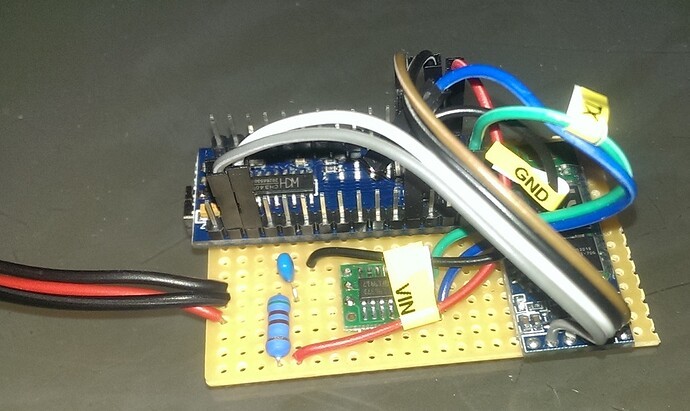
Wiring is critical in this project. The key is to correctly connect the Rx (Receiver) pin of the Bluetooth module to the Rx pin of the Arduino, and similarly, Tx (Transmitter) to Tx. It’s important to note that these connections are not crossed over. Furthermore, a pull-up resistor (around 510-550 Ohms) is required between the K-line and the VIN (voltage input) from the diagnostic port. A crucial tip for anyone replicating this project: remember to disconnect the Rx pin when uploading new code (sketch) to the Arduino to avoid conflicts during programming.
 2015-10-27 00.17.10.jpg
The Arduino Nano based OBDII Bluetooth adapter hardware, showcasing the compact design.
Software and Communication Protocols
The software aspect of this project was segmented into manageable parts. OBDII Bluetooth adapters commonly utilize the ELM327 chip (or clones), which relies on AT commands to manage communication. These commands are text-based and configure the adapter for different protocols.
AT commands begin with “AT” followed by the command, optionally a value, and end with a carriage return character (‘r’). Here are some essential AT commands used in this project:
| Command | Description | Example Response |
|---|---|---|
ATL0r |
Turn Linefeed off (disables newline characters) | OKr>r |
ATZr |
Reset the device | “ELM327 v1.4″r>r |
ATDr |
Set to default parameters | OKr>r |
ATH0/1r |
Turn Header off/on | OKr>r |
ATIr |
Request Device Info (ELM Version) | “ELM327 v1.4″r>r |
ATSPr |
Protocol Auto-detect | OKr>r |
ATS0/1r |
Turn spaces off/on | OKr>r |
ATL0/1r |
Turn linefeed off/on | OKr>r |
ATE0/1r |
Turn Echo off/on | OKr>r |
ATM0/1r |
Enable/Disable memory (store last command) | OKr>r |
The response to commands typically includes “OK” followed by carriage return and a prompt character ‘>’. However, error responses or device information may differ. For instance, the ATZ (Reset) command’s response must contain the ELM327 version information for proper initialization in some applications.
Understanding PID Lists
OBDII diagnostics relies heavily on Parameter IDs (PIDs). Data is often requested and returned in lists of 32 PIDs at a time. Requesting PID list 01, for example, involves sending the command 0100. The response is a 32-bit hexadecimal number representing 32 consecutive PIDs, where each bit indicates whether a PID is supported (1) or not (0).
Here’s an example of PID list responses:
| Request | Response |
|---|---|
0100 |
4100181B8001 |
0102 |
412000000001 |
0104 |
414008000000 |
0106 |
416000000000 |
0108 |
418000000000 |
The response format starts with 41 (indicating a valid response) followed by the requested mode (e.g., 00 for PID list 00). The subsequent hexadecimal digits represent the bitmask. For example, the response 4100181B8001 to request 0100 translates to the binary 00000100000011000000... This bitmask is then overlaid onto the standard OBDII PID list to determine supported PIDs.
A significant challenge in this project was translating standard OBDII PIDs to the Kawasaki Diagnostic System (KDS) PIDs, necessary for diagnosing Kawasaki motorcycles. Furthermore, the raw data received needed to be converted into meaningful values according to the KDS format.
Sending and Receiving Data
To request real-time data, you send a command like 010Cr (or sometimes 010C) where 01 signifies “show current data” and 0C is the PID for engine RPM. The adapter should respond with data in the format 41XXYYr>r, where XX is the requested PID (0C), and YY is the value. The value portion can be longer depending on the PID and data type.
ECU Communication and Code Integration
For deeper ECU (Engine Control Unit) communication, code from Tom Mitchell’s Kawaduino project (BitBucket) was instrumental. Kawaduino provides functions like FastInit() to initiate communication and diagnostic mode, and sendRequest() to manage request/response cycles, including checksum verification. Tom Mitchell’s YouTube demonstration (YouTube) further illustrates the application of this code.
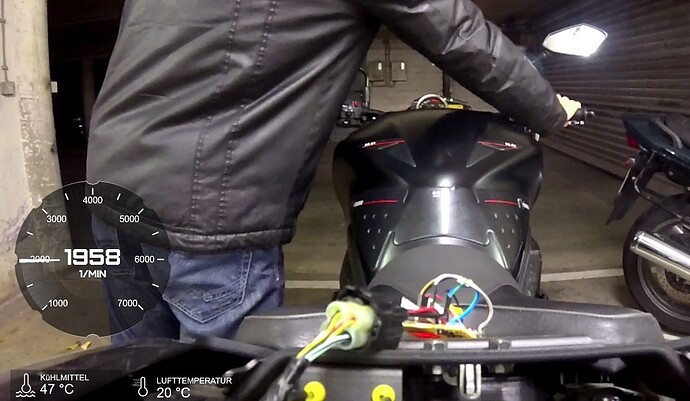
 ECU Emulator Bike-00-00-21-879.jpg
Testing the DIY OBDII Bluetooth adapter on a motorcycle, connected to the ECU.
Conclusion and Future Steps
Developing this OBDII Bluetooth adapter was a challenging yet rewarding process. Hardware issues, including incorrect Bluetooth modules and component failures, were significant initial obstacles. Software development was equally time-intensive, requiring the creation of tools for testing and analysis. To streamline the software development, an ECU emulator was built in C# to simulate ECU responses, and Bluetooth and ECU sniffers (Arduino sketches) were created to analyze communication patterns from diagnostic tools and the motorcycle’s ECU. An ECU sniffer was particularly useful for identifying supported PIDs on the motorcycle.
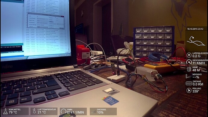
 ECU Emulator-00-00-00-000.jpg
The ECU Emulator setup, used for testing the Arduino based adapter and software.
Through trial and error, and with assistance from others with diagnostic equipment, approximately 33 KDS PIDs were identified, with another 27 still to be explored. Future work includes developing calculations for interpreting throttle position and throttle valve data. The ultimate goal is to release all project code on GitHub, including:
- ECU Emulator (Windows application)
- ECU Sniffer (Arduino sketch)
- Bluetooth Sniffer (Arduino sketch)
- ECU Reader (Arduino sketch) – the core OBDII adapter software
- PID List with formulas (Excel sheet)
This project demonstrates the feasibility of creating a DIY OBDII Bluetooth adapter with enhanced capabilities. The addition of memory card logging, while not explicitly detailed here, is a planned enhancement that will allow for offline data analysis and more comprehensive vehicle diagnostics. Stay tuned for updates and the release of project resources!
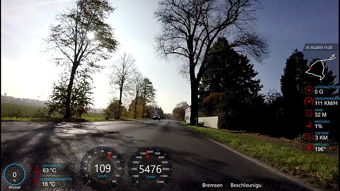
 IMG-20151031-WA0006.jpg
First successful ride using the DIY OBDII Bluetooth adapter and Garmin Virb XE action cam for data display.
