For car enthusiasts and tech-savvy individuals, understanding what’s happening under the hood goes beyond just listening to the engine. Modern vehicles are complex networks of electronics, and protocols like CAN-Bus are the language they use to communicate. This article explores how you can tap into this communication using readily available tools like the ELM327 OBD2 adapter and even create your own diagnostic interfaces using platforms like MIT App Inventor.
Understanding your car’s diagnostics system opens up a world of possibilities, from reading error codes to monitoring performance data in real-time. While professional diagnostic tools offer comprehensive features, this guide focuses on the fundamentals, showing you how to establish a connection and interpret basic data using an ELM327 adapter and a custom application. This is not intended to be a complete, professional-grade diagnostic application, but rather an educational exercise to demonstrate the principles involved in accessing and interpreting vehicle data via the CAN-Bus protocol.
Diving into OBD2, OBDII, and CAN-Bus
Before we delve into the practical aspects, let’s clarify some key terms. OBD2 (On-Board Diagnostics II) and OBDII are essentially the same, referring to the second generation of standardized automotive diagnostic systems. This standard mandates a universal connector and a set of diagnostic trouble codes (DTCs) across most vehicles, making it easier to read vehicle health information.
CAN-Bus (Controller Area Network) is the communication protocol used within the vehicle to allow different electronic control units (ECUs) to talk to each other. This network handles a vast amount of data exchange, from engine management to braking systems. The OBD2 port is your gateway to accessing this CAN-Bus network for diagnostic purposes.
Harnessing the ELM327 for CAN-Bus Diagnostics
The ELM327 chip is a popular microcontroller that acts as a bridge between your computer or mobile device and your car’s OBD2 port. ELM327 adapters are readily available and affordable, making them an excellent entry point for DIY car diagnostics. These adapters typically communicate wirelessly via Bluetooth or Wi-Fi, allowing you to connect with smartphones, tablets, or laptops.
To understand the communication flow, consider the “Man in the Middle” approach used to reverse engineer the commands. By placing a sniffer between an existing OBD2 app and the ELM327 interface, the command sequences used to wake up the car’s ECU and initiate diagnostic mode can be observed and analyzed.
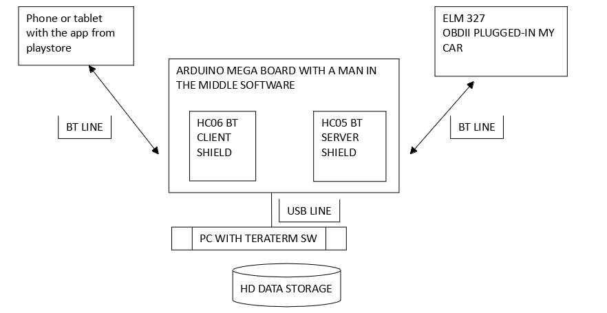 Man in the Middle
This process involves intercepting and recording data transmitted between a diagnostic app and the ELM327 adapter. An Arduino setup with serial communication can act as this sniffer, forwarding data to both the ELM327 and a computer for analysis. This method allows for the discovery of specific command sequences and response patterns, which are crucial for developing custom diagnostic applications. While not necessary for basic usage, understanding this reverse engineering approach provides valuable insight into the communication protocols at play.
Hardware Essentials
To get started with DIY CAN-Bus diagnostics using ELM327, you’ll need:
- ELM327 OBD2 Bluetooth/Wi-Fi Adapter: This is the core interface that plugs into your car’s OBD2 port and communicates wirelessly.
- Tablet or Smartphone: An 8-inch tablet is suggested in the original context for screen layout considerations, but any smartphone or tablet capable of running your chosen diagnostic software will work.
Clock Functions in a DIY Diagnostic App
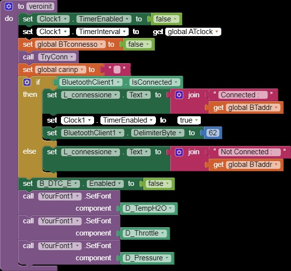
In a custom application like the one demonstrated using MIT App Inventor, timers or “Clocks” play a crucial role in managing communication with the ELM327 and the car’s ECU. Here’s a breakdown of typical clock functions:
-
Data Reception Clock (Clock1): This clock manages the incoming data stream from the ELM327. It differentiates between AT commands (ELM327 control commands) and CAN data responses, directing the data to the appropriate display procedures. It is typically activated when a command is sent and deactivated upon receiving a valid response.
-
Command Scheduling Clock (Clock2): This clock acts as a scheduler for sending CAN commands to the ELM327 at regular intervals. It ensures a continuous flow of data requests for real-time monitoring.
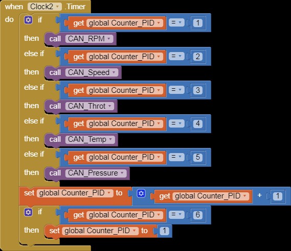 when Clock2 Timer
- DTC Retrieval Clock (Clock3): Specifically for requesting Diagnostic Trouble Codes from the ECU. This clock manages the timing for DTC requests, allowing the ECU sufficient time to prepare and transmit the data.
 when Clock3 Timer
- Initialization Clock (Clock4): This clock orchestrates the sequence of AT commands required to initialize the ELM327 adapter and establish CAN communication with the car’s ECU. It runs through a predefined sequence of initialization commands.
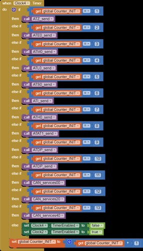 when Clock4 Timer
- Real-Time Clock (Clock5): A simple clock for displaying current time within the application interface, providing a timestamp reference.
 when Clock5 Timer
Screen Interface Overview
A basic diagnostic application interface typically includes buttons for sending specific commands and displaying received data. The layout often features:
- Command Buttons: Color-coded buttons to manually send individual diagnostic commands to the ECU. These buttons can be arranged in a sequence reflecting the initialization process or common diagnostic requests.
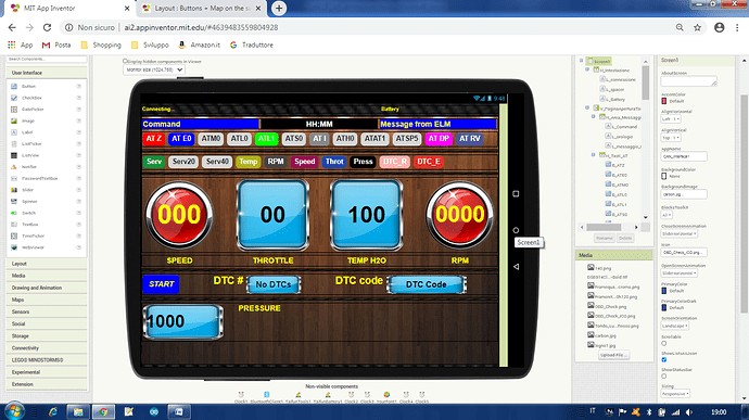 Screen
- Start/Stop Button: A key control to initiate and terminate the automated command sequence for ECU communication. This button often toggles between “START” and “STOP” labels to indicate the current state of the diagnostic session.
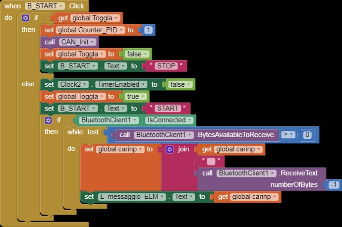 when B_START Click
- Data Display Areas: Sections of the screen dedicated to displaying real-time data received from the ECU, such as engine temperature, RPM, speed, and throttle position.
Conclusion: Empowering DIY Car Diagnostics
Using an ELM327 OBD2 adapter and understanding CAN-Bus communication opens up a fascinating area of DIY car diagnostics. While this example focuses on a simplified application built with MIT App Inventor, the principles are applicable to more advanced diagnostic tools and software development. By exploring these technologies, enthusiasts and professionals alike can gain deeper insights into vehicle systems and contribute to innovative automotive solutions. Further exploration into OBD2 standards and CAN-Bus protocols will enhance your understanding and capabilities in this domain.
