In the realm of automotive repair and diagnostics, understanding the intricate communication systems within vehicles is paramount. As a content creator for autelfrance.com, and an expert in auto repair, I aim to provide you with a comprehensive guide to navigating these systems. This article delves into the world of vehicle diagnostics, focusing on the crucial role of J1939 And Obdii Combo Control Devices. These devices are becoming increasingly essential tools for technicians working across a diverse range of vehicles, from light-duty passenger cars to heavy-duty trucks and machinery.
This guide will expand upon the foundational knowledge presented in the original article “[OBD2 Explained – A Simple Intro [2025]]” and elevate it to meet the demands of today’s evolving automotive landscape. We will explore the synergy between J1939 and OBDII protocols, the advantages of combo control devices, and how these tools are shaping the future of vehicle diagnostics, all while keeping SEO optimization for an English-speaking audience at the forefront.
Understanding OBDII and J1939: A Diagnostic Protocol Overview
Modern vehicles are complex networks of electronic control units (ECUs) communicating via various protocols. Two of the most prominent are OBDII (On-Board Diagnostics II) and J1939. While OBDII is primarily associated with light-duty vehicles and emission control, J1939 is the standard for heavy-duty vehicles and industrial applications.
What is OBDII?
OBDII is a standardized system implemented in most cars and light trucks, providing access to diagnostic information related to emissions and vehicle performance. It uses a 16-pin Data Link Connector (DLC) and allows technicians to retrieve Diagnostic Trouble Codes (DTCs), monitor real-time data parameters (PIDs), and perform various diagnostic tests.
You’ve likely encountered OBDII when your vehicle’s check engine light illuminates. This indicates a potential issue, and an OBDII scanner can be connected to the DLC, typically located under the dashboard, to diagnose the problem. The scanner sends requests, and the vehicle responds with data, enabling efficient troubleshooting.
Understanding OBD2: On-Board Diagnostics and the Malfunction Indicator Light (MIL).
What is J1939?
J1939 is a higher-level protocol that operates on the Controller Area Network (CAN) bus, specifically designed for communication within heavy-duty vehicles like trucks, buses, and construction equipment. It defines how ECUs communicate and share data related to engine, transmission, braking systems, and more. J1939 is crucial for monitoring complex systems in these larger vehicles and machinery.
While OBDII focuses heavily on emissions, J1939 provides a broader spectrum of diagnostic and control capabilities relevant to the operation and maintenance of heavy-duty equipment.
The Need for Combo Control Devices: Bridging the Diagnostic Gap
Workshops and technicians increasingly encounter a diverse range of vehicles, from passenger cars to commercial trucks. This necessitates tools capable of interacting with both OBDII and J1939 protocols efficiently. This is where j1939 and obdii combo control devices come into play.
These devices offer a unified solution, eliminating the need for separate scanners and interfaces for different vehicle types. A combo device streamlines the diagnostic process, saving time and resources for technicians.
History and Evolution of OBDII and J1939
OBDII’s Emission-Driven Origins
OBDII’s roots trace back to California’s environmental regulations. The California Air Resources Board (CARB) mandated OBD systems in new cars from 1991 onwards for emission control. The Society of Automotive Engineers (SAE) played a crucial role in standardizing OBDII, leading to consistent DTCs and connectors across manufacturers (SAE J1962).
The OBDII standard adoption timeline:
- 1996: OBDII becomes mandatory in the USA for cars and light trucks.
- 2001: Required in the EU for gasoline cars.
- 2003: Required in the EU for diesel cars (EOBD).
- 2005: OBDII mandated in the US for medium-duty vehicles.
- 2008: US vehicles must use ISO 15765-4 (CAN) for OBDII communication.
- 2010: OBDII required for heavy-duty vehicles in the US.
OBD2 History: From Emission Control to Vehicle Data Access via CAN bus.
J1939’s Heavy-Duty Focus
J1939 emerged as the standardized communication protocol for heavy-duty vehicles, driven by the need for robust and comprehensive diagnostics in commercial transportation and industrial sectors. Developed by SAE, J1939 addressed the specific requirements of complex systems in trucks, buses, and off-highway equipment.
OBDII and J1939 Standards: Key Technical Aspects
Both OBDII and J1939 rely on a set of standards that define their physical layers, data formats, and communication protocols. Understanding these standards is crucial for developing and using effective diagnostic tools, including j1939 and obdii combo control devices.
OBDII Standards Overview
OBDII standards encompass various aspects, including:
- Connector: SAE J1962 / ISO 15031-3 defines the 16-pin DLC.
- Communication Protocols: ISO 15765-4 (CAN), ISO 14230-4 (KWP2000), ISO 9141-2, SAE J1850 (VPW & PWM).
- Diagnostic Services: SAE J1979 / ISO 15031-5 outlines the 10 diagnostic modes (services) and Parameter IDs (PIDs).
OBD2 and CAN Bus Standards within the OSI Model.
J1939 Standards Overview
J1939 standards are a suite of documents, including:
- J1939-11: Physical Layer (defines the CAN physical layer).
- J1939-21: Data Link Layer (defines data packaging and transmission).
- J1939-71: Vehicle Application Layer (defines Parameter Groups and Suspect Parameter Numbers – SPNs).
- J1939-73: Diagnostic Layer (defines diagnostic message formats and services).
The OBDII Connector: Your Access Point
The 16-pin OBDII connector, standardized by SAE J1962, is the physical interface for accessing vehicle diagnostic data. It’s typically located within reach of the driver’s seat, though its exact location can vary.
Key features of the OBDII connector:
- Pin 16: Battery power supply.
- Pins 4 & 5: Ground.
- Pins 6 & 14: CAN High (CAN-H) and CAN Low (CAN-L), for CAN bus communication (most common protocol).
OBD2 Connector Pinout (Type A) – Standard Data Link Connector (DLC).
OBDII Connector Types: A vs. B
While Type A is standard in cars, Type B OBDII connectors are found in medium and heavy-duty vehicles. Type B features an interrupted groove and often supports 24V systems, while Type A is typically 12V. Type B adapters are often compatible with both Type A and B sockets, but Type A adapters may not fit Type B sockets.
OBD2 Connector Types A and B: Distinctions for Cars and Heavy Vehicles.
OBDII and CAN Bus: The Communication Backbone
Since 2008, CAN bus (ISO 15765-4) has been the mandatory physical layer for OBDII in US vehicles. ISO 15765-4, also known as Diagnostics over CAN (DoCAN), specifies parameters for CAN implementation in OBDII, including:
- Bit-rate: 250K or 500K.
- CAN IDs: 11-bit or 29-bit.
- Specific CAN IDs: Reserved for OBDII requests and responses.
- Data Length: 8 bytes per CAN frame.
- Cable Length: Max 5 meters for OBDII adapter cables.
OBD2 and CAN bus: Relationship based on ISO 15765 Standards.
OBDII CAN Identifiers
OBDII communication involves request and response messages over the CAN bus.
-
11-bit CAN IDs:
- Functional Addressing Request: 0x7DF (broadcast request to all OBDII ECUs).
- Physical Addressing Request: 0x7E0-0x7E7 (directed requests to specific ECUs).
- Response IDs: 0x7E8-0x7EF (responses from ECUs, e.g., 0x7E8 for Engine Control Module – ECM).
-
29-bit CAN IDs: Used in some heavy vehicles.
- Functional Addressing Request: 0x18DB33F1.
- Response IDs: 0x18DAF100 to 0x18DAF1FF (e.g., 0x18DAF110, 0x18DAF11E), also represented as J1939 PGN 0xDA00 (55808).
OBD2 Request and Response Frames: Structure with Mode, PID, and Data.
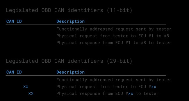 OBD2 OBD CAN bus Identifiers 7DF 7E8 7E0
OBDII vs. Proprietary CAN Protocols
It’s crucial to understand that OBDII is a diagnostic protocol layered on top of a vehicle’s core communication network. OEMs implement their proprietary CAN protocols for ECU-to-ECU communication and vehicle operation. OBDII is an additional layer designed for standardized diagnostics.
Connecting a CAN bus data logger to the OBDII port may capture OEM-specific CAN data, but often a gateway restricts access, allowing only OBDII communication through the port.
OBD2 vs. OEM-Specific CAN Bus: Diagnostic Layer vs. Vehicle Operation Network.
Bit-rate and ID Validation for OBDII
OBDII may use 250K or 500K bit-rates and 11-bit or 29-bit CAN IDs. Diagnostic tools, including j1939 and obdii combo control devices, must automatically detect and validate these settings. ISO 15765-4 provides a validation sequence to determine the correct combination by sending a mandatory OBDII request and checking for responses and CAN errors.
OBD2 Bit-rate and CAN ID Validation Flowchart (ISO 15765-4).
Five Lower-Layer OBDII Protocols (Historical Context)
While CAN is dominant today, older vehicles used other protocols for OBDII:
- ISO 15765 (CAN): Modern standard, mandatory in US since 2008.
- ISO 14230-4 (KWP2000): Common in 2003+ Asian vehicles.
- ISO 9141-2: Used in EU, Chrysler, and Asian vehicles (2000-04).
- SAE J1850 VPW: Primarily older GM vehicles.
- SAE J1850 PWM: Primarily older Ford vehicles.
Five Lower-Layer OBD2 Protocols: Including CAN, KWP2000, SAE J1850, and ISO 9141.
ISO-TP for OBDII Multi-Frame Messages
OBDII utilizes ISO-TP (ISO 15765-2) as a transport protocol over CAN to handle messages larger than 8 bytes. This is essential for transmitting data like VIN or DTCs. ISO-TP manages segmentation, flow control, and reassembly of messages. For shorter messages, OBDII uses ‘Single Frame’ (SF) format within ISO-TP.
ISO 15765-2 Frame Types for OBD2 Communication (ISO-TP).
The OBDII Diagnostic Message Structure
An OBDII message on CAN, in its simplest form, comprises an identifier, data length (PCI field), and data payload. The data payload contains the Mode, Parameter ID (PID), and data bytes.
OBD2 Message Structure: Breakdown of a Raw CAN Frame.
Example: OBDII Request and Response for Vehicle Speed
Consider a request for Vehicle Speed:
- Request: CAN ID 0x7DF, Payload: Mode 0x01, PID 0x0D.
- Response: CAN ID 0x7E8, Payload: Mode 0x41 (0x01 + 0x40), Data byte 4: 0x32 (decimal 50).
Decoding PID 0x0D reveals a vehicle speed of 50 km/h.
OBD2 Request and Response Example: CAN IDs 0x7DF and 0x7E8.
OBD2 PID Example: Vehicle Speed (PID 0x0D).
The 10 OBDII Services (Modes)
OBDII defines 10 diagnostic services or modes (SAE J1979 / ISO 15031-5). Mode 0x01 provides real-time data, while others handle DTCs, freeze frame data, etc. Vehicles may not support all modes and can have OEM-specific modes.
In messages, the mode is the second byte. Responses add 0x40 to the requested mode (e.g., request 0x01, response 0x41).
OBD2 Diagnostic Services (Modes): Overview of the 10 Standardized Modes.
OBDII Parameter IDs (PIDs)
Each OBDII mode contains Parameter IDs (PIDs). Mode 0x01, for example, has ~200 standardized PIDs for real-time data like speed, RPM, and fuel level. However, vehicles support only a subset of these PIDs.
A crucial PID is Mode 0x01 PID 0x00. All emissions-related ECUs supporting OBDII services must support this PID. Responding to PID 0x00 indicates support for PIDs 0x01-0x20. PIDs 0x20, 0x40, etc., similarly indicate support for subsequent PID ranges within Mode 0x01. PID 0x00 is a fundamental OBDII compatibility test.
OBD2 Request and Response Frames: Detailed View with Mode, PID, and Data Bytes.
OBDII PID Overview Tool
SAE J1979 and ISO 15031-5 appendices detail scaling information for standard OBDII PIDs, enabling data decoding into physical values. Online OBDII PID overview tools can assist in constructing requests and decoding responses.
OBD2 PID overview tool
Logging and Decoding OBDII Data: A Practical Guide
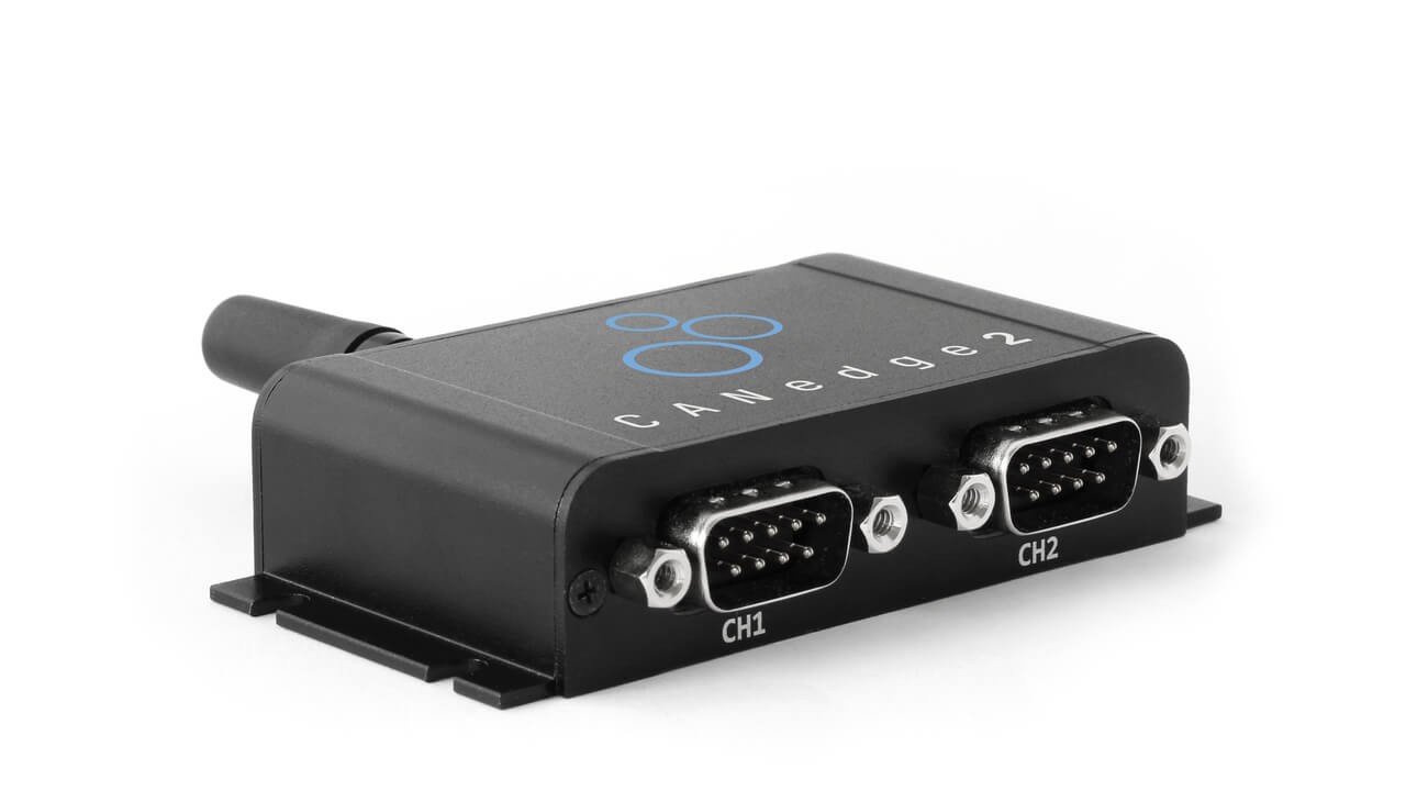
Tools like the CANedge CAN bus data logger can be used to log OBDII data. These devices allow custom CAN frame transmission for OBDII requests. Combined with an OBDII-DB9 adapter cable, they can interface with vehicles easily. J1939 and OBDII combo control devices often incorporate similar logging capabilities alongside broader protocol support.
OBD2 Data Logger Setup: Requesting PIDs via CAN frames (IDs 0x7DF and 0x7E8).
Step #1: Validate Bit-rate, IDs, and Supported PIDs
ISO 15765-4 outlines a process to determine the correct bit-rate and CAN IDs. CANedge (and similar tools) can be used to test:
- Send CAN frame at 500K; check for success (else try 250K).
- Use validated bit-rate for communication.
- Send ‘Supported PIDs’ requests and analyze responses.
- Response IDs indicate 11-bit or 29-bit CAN IDs.
- Response data reveals supported PIDs.
Plug-and-play configurations are often available to automate these tests. Most post-2008 non-EV cars support 40-80 PIDs using 500K bit-rate, 11-bit CAN IDs, and OBDII/OBDonEDS protocol.
 OBD2 bit rate test
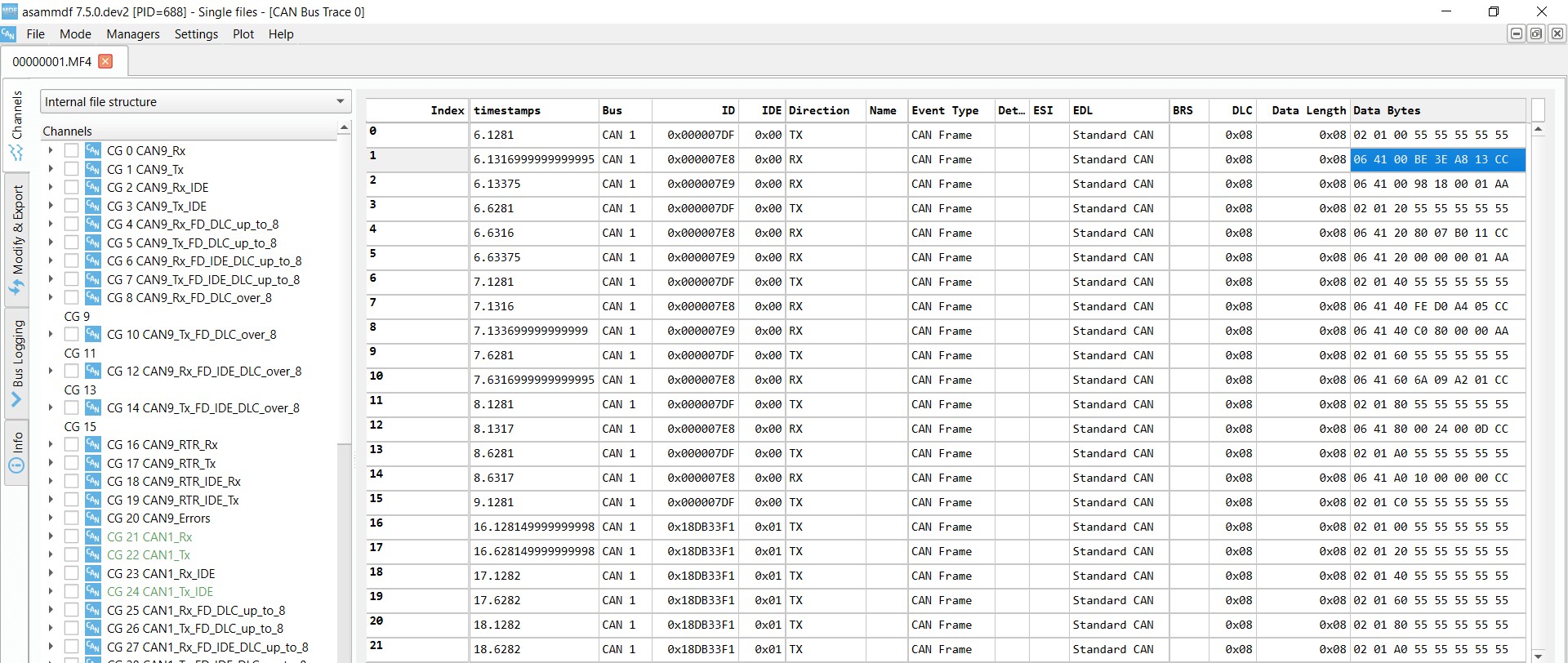 OBD2 Supported PIDs Test
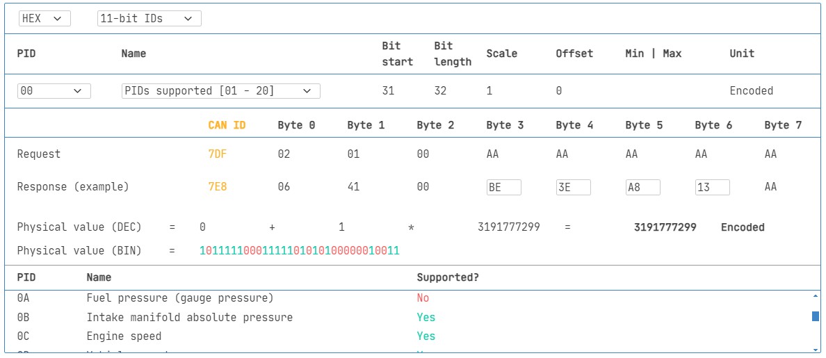 Review supported PIDs via OBD2 lookup tool
Step #2: Configure OBDII PID Requests
Once you know supported PIDs and communication parameters, configure your device (like a j1939 and obdii combo control device) to request specific PIDs.
Considerations:
- CAN IDs: Use Physical Addressing IDs (e.g., 0x7E0) to target specific ECUs.
- Spacing: Add 300-500 ms delay between requests to avoid ECU overload.
- Power Management: Implement triggers to stop requests when the vehicle is inactive (prevent battery drain).
- Filtering: Filter for OBDII responses if OEM-specific CAN data is also present.
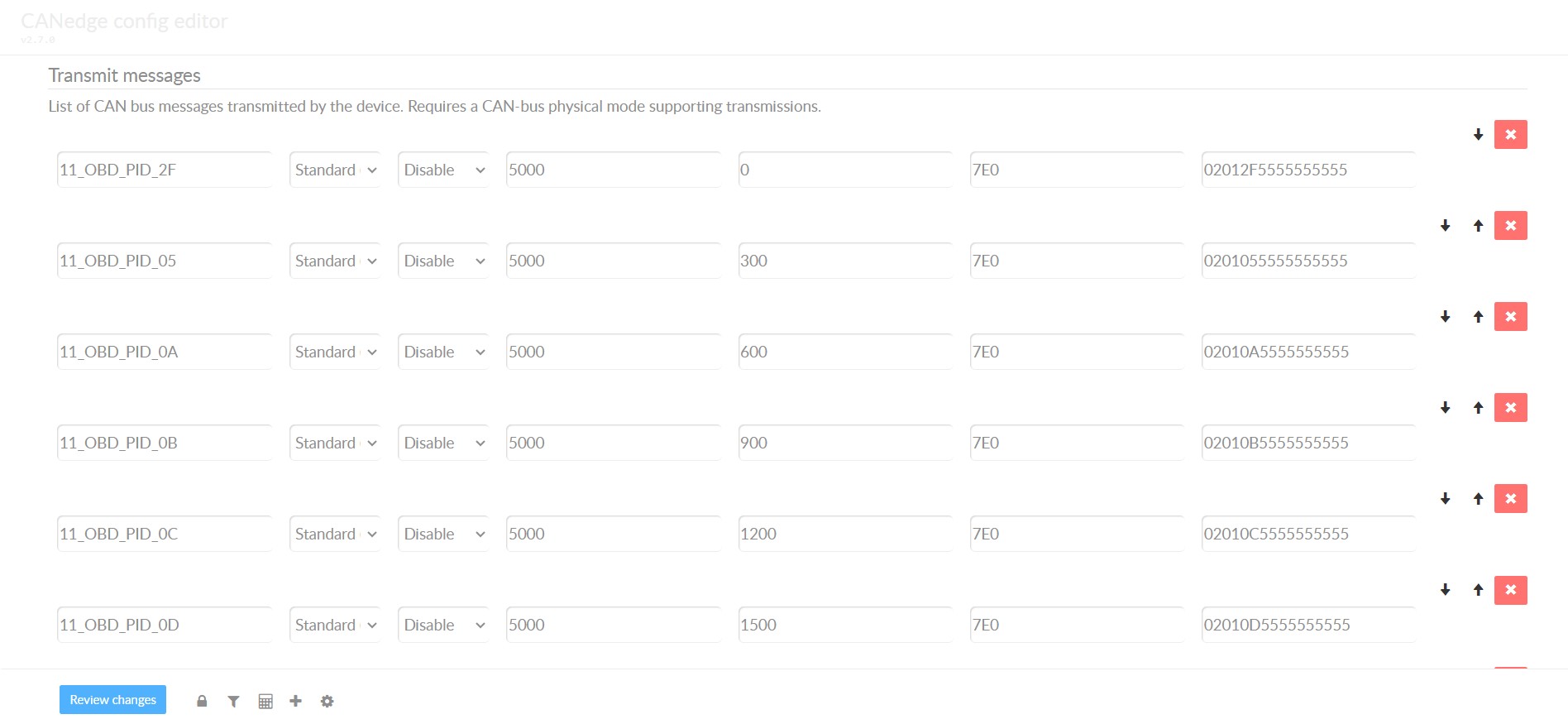 obd2-transmit-list-example-canedge
Step #3: DBC Decode Raw OBDII Data
To interpret logged OBDII data, decode raw CAN data into physical values. ISO 15031-5/SAE J1979 and online resources (like Wikipedia) provide decoding information. A free OBDII DBC file simplifies DBC decoding in CAN bus software tools.
OBDII decoding is complex because different PIDs share the same CAN ID (e.g., 0x7E8). Decoding requires using CAN ID, OBDII mode, and PID – a form of ‘extended multiplexing’. DBC files can implement this logic.
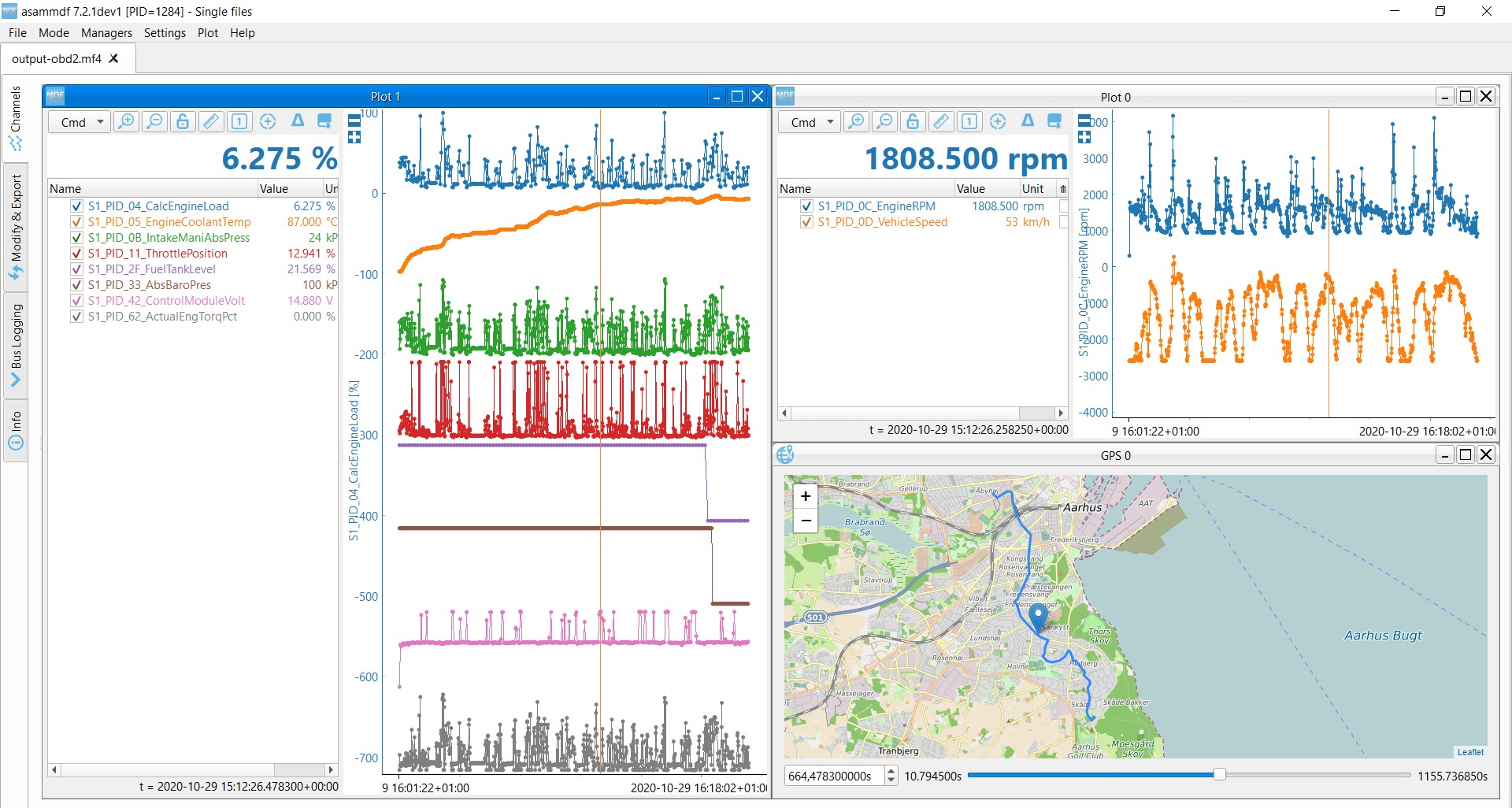 OBD2 data decoded visual plot asammdf CAN bus DBC file
OBDII Multi-Frame Examples (ISO-TP)
OBDII uses ISO-TP for multi-frame communication. Examples include retrieving VIN and handling multi-PID requests and DTCs. Multi-frame communication often requires flow control frames.
 OBD2-multi-frame-request-message-vehicle-identification-number
Example 1: Vehicle Identification Number (VIN) Retrieval
To get the VIN using OBDII: Mode 0x09, PID 0x02.
 VIN Vehicle Identification Number OBD2 Example multi-frame
Example 2: Multi-PID Request (6x)
OBDII allows requesting up to 6 Mode 0x01 PIDs in a single request. The ECU responds with data for supported PIDs, possibly across multiple frames. While efficient, this method makes generic DBC file use complex due to request-specific signal encoding.
 Requesting multiple PIDs in one request
Example 3: Diagnostic Trouble Codes (DTCs)
Mode 0x03 (‘Show stored DTCs’) retrieves emissions-related DTCs. No PID is needed in the request. Responses include the number of DTCs and the 2-byte DTC codes. Multi-frame responses are necessary for more than 2 DTCs. DTC codes are structured according to ISO 15031-5/ISO 15031-6 and can be looked up using OBDII DTC lookup tools.
OBD2 DTC Decoding: Interpretation of Diagnostic Trouble Code Bytes.
 OBD2 Diagnostic Trouble Codes DTC CAN Bus Request Response Example
OBDII Data Logging Use Cases
OBDII data logging has diverse applications:
OBD2 Data Logger in Vehicle: On-Board Diagnostics Applications.
- Car Data Logging: Fuel cost reduction, driving improvement, prototype testing, insurance telematics.
- Real-time Car Diagnostics: Streaming OBDII data for immediate issue diagnosis.
- Predictive Maintenance: IoT-connected OBDII loggers for preemptive maintenance.
- Vehicle Black Box: OBDII loggers as ‘black boxes’ for accident analysis and diagnostics.
OBD2 Real-time Streaming Diagnostics via USB Interface.
OBD2 Data Logger for Predictive Maintenance and Telematics.
CAN Bus Data Logger as a Vehicle Black Box.
Conclusion: Embracing Universal Vehicle Diagnostics
J1939 and OBDII combo control devices represent a significant advancement in vehicle diagnostics. By integrating support for both light-duty (OBDII) and heavy-duty (J1939) protocols, these tools offer workshops and technicians unparalleled versatility and efficiency. As vehicle technology continues to evolve, the ability to diagnose and service a wide spectrum of vehicles with a single, comprehensive tool will become increasingly critical. Investing in j1939 and obdii combo control devices is not just about keeping up with current diagnostic needs; it’s about preparing for the future of automotive repair.
Do you have an OBDII or J1939 data logging use case? Reach out for expert consultation!
Contact us
Explore our guides section for more introductory articles or download the ‘Ultimate Guide’ PDF for in-depth knowledge.
Need to log or stream OBDII/J1939 data?
Get your universal vehicle diagnostic tool today!
Buy now Contact us
Recommended for you
OBD2 DATA LOGGER: EASILY LOG & CONVERT OBD2 DATA
 CANedge2 – Dual CAN Bus Telematics Dongle CANEDGE2 – PRO CAN IoT LOGGER
[
