
This post details the progress on building a custom Heads Up Display (HUD) for automotive use, specifically focusing on establishing a reliable OBDII connection and testing key components. The goal is to create a system that can display crucial vehicle data directly in the driver’s line of sight, enhancing safety and providing real-time information.
Initially, testing began with an OLED screen intended for data display. However, the initial OLED screen exhibited issues. Despite successful initialization using DIYMall libraries, the display only showed random lit pixels that would not turn off after initialization. This indicated a likely hardware malfunction, rendering it unusable for the project. To ensure project continuity, a replacement OLED screen was ordered. The chosen replacement, favored for its positive reviews and compatibility with the Adafruit OLED screen library, promises a smoother integration and better performance.
For electrical safety and component protection, a decision was made to incorporate a fuse into the +12V power line originating from the car. Instead of a standard automotive fuse, a 2A fast blow fuse was selected along with 5x20mm fuse PCB mounts. This choice allows for rapid response to overcurrent conditions, safeguarding the delicate electronics of the HUD system. The use of PCB mounts also facilitates easy fuse replacement and a cleaner, more organized wiring setup.
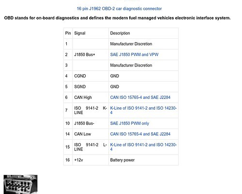
A significant part of the project update involves testing the OBDII extension cable. The OBDII port is the gateway to accessing vehicle data, making a reliable connection paramount. The first step was to identify the relevant pins on the car-side OBDII connector. Analysis of the standard OBDII pinout revealed that only five pins are essential for this project: +12V for power, Chassis Ground, Signal Ground, CAN High, and CAN Low for data communication. These pins are crucial for powering the HUD and receiving vehicle data via the Controller Area Network (CAN) bus.
Next, the focus shifted to the OBDII extension plug itself. Careful examination of the plug’s pin labels was conducted to locate the five pins of interest. A multimeter was then employed to trace each pin to its corresponding wire within the extension cable. This methodical approach ensures accurate identification and labeling of each wire, preventing wiring errors that could damage the vehicle’s ECU or the HUD system. Once identified, each wire was clearly labeled with tape and a marker, streamlining the subsequent wiring and connection process.
[
[
[
[
In a separate exploration for HUD components, an interesting possibility emerged. Scope lens protectors, typically used for gun sights, were identified as a potential solution for the HUD’s projection element. These small pieces of transparent material, designed to mount on rails in front of gun sights, could potentially serve as a compact and effective display surface for projecting the OBDII data. This idea offers a unique approach to the HUD design and warrants further investigation into its feasibility and optical characteristics.
Next Steps:
The immediate next steps involve connecting the meticulously prepared OBDII extension plug to the car’s OBDII port. This connection will enable thorough testing of the identified pins and ensure proper communication with the vehicle’s computer. Simultaneously, the arrival and testing of the new OLED screen are anticipated, which will be crucial for verifying the display functionality of the HUD system. These tests will validate the groundwork laid and pave the way for further development of the Heads Up Obdii display project.