
The goal of this project is to build a heads-up display (HUD) using a Bluetooth OBDII adapter and an OLED screen. This will allow vehicle data to be displayed directly in the driver’s line of sight. This post details the initial steps taken, including component selection, wiring, and testing.
Initial Component Selection and Testing
The first attempt at using an OLED screen proved unsuccessful. After initializing it with DIYMall libraries, only random pixels would light up and wouldn’t turn off.
A replacement OLED screen with positive reviews and compatibility with the Adafruit OLED screen library was ordered from Amazon: Amazon.com: OLED Display Module.
To protect the system, a 2A fast blow fuse and 5x20mm fuse PCB mounts were also added to the +12V power line from the car. These components were sourced from Amazon as well: Amazon.com: Fast Blow Fuses and Amazon.com: Fuse Mounts.
OBDII Extension Cable Wiring
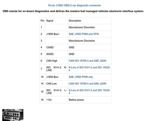
To prepare for connecting to the vehicle’s OBDII port, an extension cable was analyzed. The car-side OBDII connector pinout was referenced to identify the necessary pins: +12V, Chassis Ground, Signal Ground, CAN High, and CAN Low.
Using a multimeter, each wire on the OBDII extension plug was matched to its corresponding pin. Each wire was then labeled for clarity.
Exploring HUD Display Solutions
Research led to the discovery of scope lens protectors used for gun sights. These are small pieces of glass or plastic mounted on a rail in front of the sight. This concept might be adaptable for the HUD element of the project.
Next Steps
The next steps in the project include connecting the modified OBDII extension cable to the car’s OBDII port to verify the connections and testing the functionality of the new OLED screen.