Creating a custom head up display (HUD) using an OBDII scanner and an OLED screen can provide real-time vehicle information directly in the driver’s line of sight. This project involves connecting an OBDII extension cable, utilizing a new OLED screen, adding a fuse for safety, and potentially incorporating a scope lens for projection.
An initial attempt using a DIYMall OLED screen proved unsuccessful, resulting in random pixel behavior. A replacement OLED compatible with the Adafruit library was chosen based on positive reviews (Amazon Link).
To enhance safety, a 2A fast blow fuse and corresponding PCB mounts were incorporated into the +12V power line from the vehicle’s OBDII port (Fuse Link, Mount Link).
Decoding the OBDII Connection for the Head Up Display OBDII
A crucial step in building a Head Up Display Obdii system is understanding the OBDII connector pinout. The project focused on five essential pins: +12V, Chassis Ground, Signal Ground, CAN High, and CAN Low. Consulting a pinout diagram (OBDII Pinout Diagram) allowed for accurate identification and labeling of these wires on the OBDII extension cable using a multimeter.
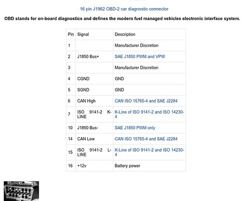 alt text: OBDII connector pinout diagram highlighting relevant pins for a head up display project.
Each wire within the OBDII extension cable was meticulously identified and labeled for proper connection. This process involved cross-referencing the pinout diagram with the physical connector, ensuring accurate mapping of signals.
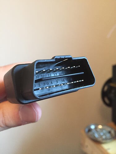 alt text: Close-up image of an OBDII extension cable with labeled wires for +12V, ground, and CAN signals.
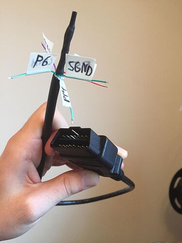 alt text: Labeled OBDII connector with clear markings for power, ground, and CAN High/Low pins, essential for a head up display obdii project.
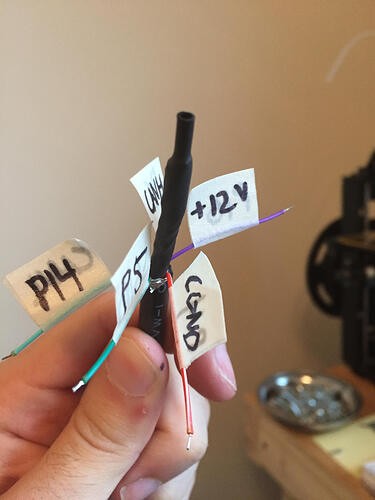 alt text: Detailed view of an OBDII extension cable with individually labeled wires ensuring correct connection to the head up display obdii system.
Exploring HUD Projection Using a Scope Lens
Research revealed a potential solution for projecting the OLED display: a scope lens protector typically used for gun sights. This component, featuring a small piece of glass or plastic on a rail mount, could offer a method for reflecting the display onto the windshield.
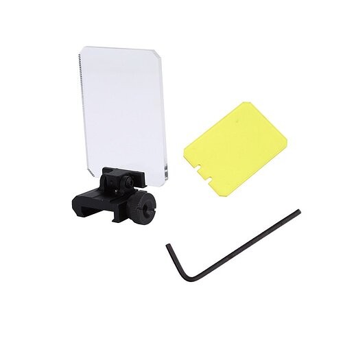 alt text: A scope lens protector, typically used on firearms, could be repurposed for projecting the OLED display in a head up display obdii system.
The next steps involve testing the OBDII connection in the vehicle and evaluating the new OLED screen’s functionality. The feasibility of integrating the scope lens for projection will also be explored. This head up display obdii project showcases the potential of creating a custom HUD system by combining readily available components with innovative solutions.
