This guide provides a detailed walkthrough for creating your own OBDII to USB cable. This project is perfect for car enthusiasts looking to save money and gain a deeper understanding of their vehicle’s diagnostics. Disclaimer: This guide is based on personal experience and is not professional advice. Proceed at your own risk.
Gathering Your Supplies
Before you begin, ensure you have the following tools and parts:
- Tools:
- Wire strippers/cutters
- Needle-nose pliers
- Soldering iron (recommended)
- Molex crimping tool (optional)
- Parts:
- 4-pin connector (22-16AWG wire size, 1.3-1.7mm insulation/seal size)
- OBD-II Cable (female connector)
You can purchase a pre-made OBDII connector with wires, or source individual components. If using spare wire, ensure the 4-pin connector matches the wire gauge.
Understanding the OBDII Connector
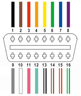
A standard OBDII connector (OBD2C) has 16 pins. For this Diy Obdii To Usb Cable project, we’ll only use four:
- Pin 4: Chassis Ground (Orange wire)
- Pin 6: CAN (J-2234) High (Green wire)
- Pin 14: CAN (J-2234) Low (Brown with white stripe wire)
- Pin 16: Battery Power (Green with white stripe wire)
Building Your Cable: A Step-by-Step Guide
Step 1: Prepare the OBDII Cable
Remove the outer sheath and shielding from the OBD2C, exposing the wires. Separate the four necessary wires (pins 4, 6, 14, and 16) and secure the remaining wires with a zip tie.
Step 2: Prepare the Wires for the 4-Pin Connector
If the OBD2C wires are thinner than the 4-pin connector (4PC) pins, strip and double them over to create a thicker gauge. Slide a rubber seal onto each wire.
Step 3: Connect the Wires to the 4-Pin Connector Pins
Insert the exposed wire into the first set of prongs on the 4PC pin. Use needle-nose pliers if necessary to hold the wire in place.
Step 4: Secure the Connection (Soldering Recommended)
Soldering provides a more secure connection. Solder the wire to the pin.
Step 5: Crimp the Connector (Alternative to Soldering)
If you have a Molex crimping tool, crimp the connector prongs over the wire. If not, use needle-nose pliers to carefully fold the prongs over the wire.
Step 6: Secure the Rubber Seal
Slide the rubber seal up to the back prongs and crimp them over the seal using the same method as Step 5.
Step 7: Pair and Twist the Wires
Pair and twist the following wires:
- Pin 4 (Orange) with Pin 16 (Green/White)
- Pin 6 (Green) with Pin 14 (Brown/White)
Step 8: Connect the Pins to the 4-Pin Connector Housing
Insert the pins into the 4PC housing in the following order:
- Pin 14 (Brown/White) into slot A
- Pin 6 (Green) into slot B
- Pin 16 (Green/White) into slot C
- Pin 4 (Orange) into slot D
Push each pin through the back of the connector until it clicks into place.
Final Product and Testing
Your DIY obdii to usb cable is complete!
Connect your cable to your vehicle’s OBDII port and a USB interface (requires additional hardware and software not covered in this guide) to test its functionality.