The On-Board Diagnostics II (OBDII) system in modern vehicles is a powerful tool for understanding your car’s health. And with the advent of affordable Bluetooth Obdii Interfaces, accessing this data has never been easier. This guide delves into the world of DIY car diagnostics, focusing on how you can use a bluetooth obdii interface, specifically the ELM327, to connect to your car’s Engine Control Unit (ECU) and retrieve valuable information. While numerous comprehensive diagnostic apps exist, this exploration will focus on the foundational steps, empowering you to potentially build your own custom solutions and understand the inner workings of your vehicle.
Understanding Bluetooth OBDII Interfaces and the ELM327
OBDII, a standardized system, provides access to a wealth of data regarding your vehicle’s performance and status. A bluetooth obdii interface acts as a bridge, translating your car’s diagnostic language into data that can be interpreted by devices like smartphones, tablets, or computers via Bluetooth. The ELM327 chip is a popular and versatile microcontroller that serves as the core of many of these interfaces. It’s widely supported and compatible with various OBDII protocols, making it a go-to choice for DIY enthusiasts and professionals alike.
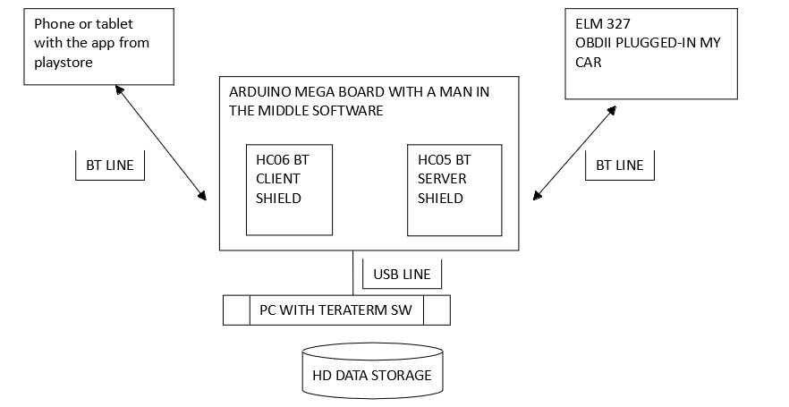
 Man in the Middle Diagram illustrating the Man-in-the-Middle technique for OBDII command analysis.
The beauty of using a bluetooth obdii interface lies in its wireless nature and affordability. These interfaces eliminate the need for cumbersome cables, allowing for convenient data access. Combined with readily available apps or custom-built software, they unlock a range of possibilities, from reading diagnostic trouble codes (DTCs) to monitoring real-time engine parameters.
Project Blueprint: ECU Connection with ELM327 and App Inventor
This guide is inspired by a project demonstrating how to establish a connection with a car’s ECU using an ELM327 bluetooth obdii interface and MIT App Inventor 2 (AI2). It’s crucial to understand that the aim isn’t to create a fully featured diagnostic application, but rather to illustrate the fundamental principles of communication and data retrieval. This project serves as an educational exercise, showcasing the potential for customized automotive interfaces.
The command sequences required to “wake up” a car’s ECU and initiate diagnostic mode can be deciphered using a “man-in-the-middle” technique. This involves intercepting the communication between an existing OBDII app and the ELM327 interface to analyze the commands being exchanged. This reverse-engineering approach allows us to understand the necessary steps for establishing communication in our own applications.
Essential Hardware for Your Project
To embark on this DIY diagnostic journey, you’ll need a few key components:
- ELM327 Bluetooth OBDII Interface: These are widely available online at affordable prices. Ensure compatibility with your vehicle’s OBDII protocol.
- Android Tablet or Smartphone: An Android device is needed to run apps built with MIT App Inventor 2 and communicate with the bluetooth obdii interface.
Software Setup: MIT App Inventor 2
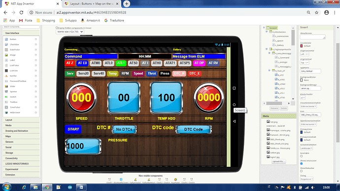
MIT App Inventor 2 is a user-friendly, block-based programming platform ideal for creating Android applications. Its visual interface simplifies the development process, making it accessible even to those with limited coding experience. For this project, AI2 will be used to build a basic app capable of sending commands to the ELM327 bluetooth obdii interface and displaying the data received from the car’s ECU.
App Functionality: Timers, Communication, and Data Handling
The example app utilizes a series of timers (Clocks in AI2) to manage different aspects of communication with the bluetooth obdii interface and the car’s ECU. Let’s break down the role of each timer:
-
Clock1 (Data Receiving): This timer is responsible for continuously monitoring for incoming data from the ELM327. It distinguishes between responses to AT commands (ELM327 commands) and CAN commands (ECU requests). It displays AT command responses directly and processes CAN data for display. Clock1 is enabled when a command is sent and disabled upon receiving a valid response.
-
Clock2 (Command Scheduler): Clock2 acts as a scheduler for sending CAN commands to the ECU at regular intervals. It starts after the initialization sequence (managed by Clock4) and repeats indefinitely until stopped by user action.
-
Clock3 (DTC Retrieval): This timer is designed to specifically request Diagnostic Trouble Codes from the ECU. It’s included to demonstrate DTC retrieval functionality, although testing in a real car environment might be necessary for full validation.
-
Clock4 (Initialization Sequence): Clock4 orchestrates the initial setup process, sending a sequence of AT commands to initialize the ELM327 bluetooth obdii interface and establish CAN communication with the car’s ECU. This timer runs only once at startup.
-
Clock5 (Time Display): A simple utility timer to display current time on the app’s screen.
 Screen Screenshot of the App Inventor interface displaying the layout of the car diagnostic app.
The app’s Bluetooth communication logic is designed to ensure complete message reception. It waits for a specific termination character (“>”) to identify the end of a response. Error handling is basic but functional, discarding empty messages and validating CAN responses against the sent commands.
Code Block Insights
Visual programming in App Inventor makes the code logic quite transparent. Here are a few key code blocks illustrating the app’s functionality:
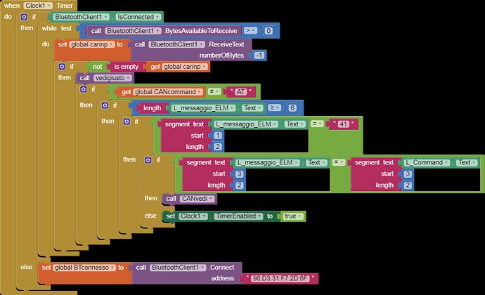
 when Clock1 Timer App Inventor code block for Clock1 Timer, handling data reception from the Bluetooth OBDII interface.
The when Clock1 Timer block is central to receiving and processing data. It checks for available bytes from the Bluetooth client and reads the response. It then determines if the response is related to an AT command or a CAN command and calls the appropriate procedures for data display and handling.
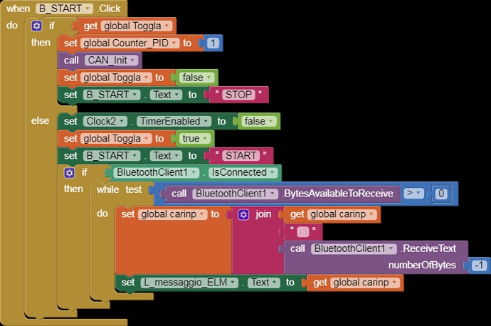
 when B_START Click App Inventor code block triggered by the Start button, initiating the ECU communication sequence.
The when B_START Click block initiates the communication sequence by starting Clock4, which handles the ELM327 and ECU initialization. This block also toggles the button’s text between “START” and “STOP” to control the data acquisition process.
Expanding Your Diagnostic Capabilities
This project provides a starting point for building more sophisticated DIY car diagnostic tools using a bluetooth obdii interface. Potential enhancements include:
- Expanding Diagnostic Functions: Implement more OBDII service modes to retrieve a wider range of data, such as live sensor readings, freeze frame data, and vehicle information.
- User Interface Improvements: Design a more intuitive and user-friendly interface for data visualization and interaction. Consider incorporating graphs, gauges, and customizable dashboards.
- Error Handling and Robustness: Enhance error handling to gracefully manage communication issues and invalid responses. Implement more robust data validation and filtering.
- Protocol Support: Explore and implement support for different CAN protocols and baud rates to increase compatibility with various vehicle makes and models.
Conclusion: Empowerment Through DIY Diagnostics
Using a bluetooth obdii interface opens up exciting possibilities for understanding and interacting with your vehicle’s systems. This project demonstrates the fundamental steps involved in establishing communication with your car’s ECU and retrieving diagnostic data. By leveraging tools like the ELM327 and MIT App Inventor, you can embark on a journey of automotive exploration, building your own custom diagnostic solutions and gaining deeper insights into your car’s inner workings. The accessibility and affordability of these technologies empower car enthusiasts and DIYers to take control of their vehicle diagnostics and maintenance.
