On-Board Diagnostics II (OBDII) compliance is a crucial aspect of modern vehicle repair and diagnostics. In Australia, OBDII became mandatory for all vehicles manufactured from January 1, 2006. This standard ensures that vehicles have a standardized diagnostic system, making it easier for mechanics and technicians to identify and address issues. However, the landscape of OBDII compliance in Australia is not always straightforward, especially when considering vehicles manufactured before 2006 or those imported into the country.
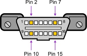
One of the first steps to determine if a vehicle is Australian Obdii Compliant is to visually inspect the OBD port. A compliant vehicle will feature a standardized 16-pin SAE J1962 connector. This port is typically located within easy reach, often under the dashboard on the driver’s side. The shape and pin count of this connector are key indicators.
 OBDII Connector Shape and Pin Count
Alt text: Diagram of a standard female OBDII connector, highlighting the 16 pin slots for vehicle diagnostic communication, used in Australian OBDII compliant vehicles.
Beyond the connector shape, the configuration of pins within the OBDII port can reveal the communication protocol used by the vehicle. While the presence of an SAE J1962 connector is a good starting point, it’s not a definitive guarantee of OBDII compliance. Some pre-OBDII vehicles also utilized this connector style. To further ascertain OBDII compliance and understand the diagnostic protocol, examining the active pin locations (those containing metal pins) is essential. Here are some common protocols and their corresponding pin configurations:
Common OBDII Protocols and Pin Configurations:
-
J1850 VPW (Variable Pulse Width Modulation): This protocol, common in General Motors (GM) vehicles, can be identified by metallic pins in positions 2, 4, 5, and 16, but crucially, not in position 10. Given GM’s historical stake in SAAB, this protocol is relevant to consider for some vehicles in the Australian market.
-
J1850 PWM (Pulse Width Modulation): Distinguished by metallic pins in positions 2, 4, 5, 10, and 16, this was a standard protocol for Ford models up to 2003 equipped with the EEC-V engine management system. This includes a range of Ford models sold in the UK and potentially imported into Australia, such as the Ford Cougar, Puma, Fiesta Zetec, Mondeo Zetec, and Focus up to 2003, as well as early Jaguar S-Type and X-Type models based on Ford platforms.
-
ISO 9141-2 / KWP2000 (Keyword Protocol 2000): This widely used protocol, found in Chrysler vehicles (which also sometimes used J1850 VPW) and numerous European and Asian makes, is characterized by metallic pins in positions 4, 5, 7, 15, and 16. It’s a significant protocol to consider for vehicles in Australia, especially those of European origin, as it was a prevalent standard before CAN-BUS became dominant. It’s worth noting that for ISO/KWP2000 communication, pin 15 (L-line) may not always be present or required, particularly in later implementations where communication primarily occurs through pin 7 (K-Line).
-
ISO 14230-4 KWP2000: Similar to ISO 9141-2, this protocol also uses metallic pins in positions 4, 5, 7, 15, and 16. It is a very common protocol for vehicles from 2003 onwards that utilize the ISO9141 K-Line communication. Like ISO 9141-2, pin 15 may not be essential in all implementations. Two variations exist, differing only in communication initialization methods (5 baud init and fast init), both operating at 10.4 Kbaud.
-
CAN-BUS (Controller Area Network) – ISO 15765-4: The most modern and prevalent protocol, CAN-BUS is mandatory for all vehicles sold in the US from 2008 onwards and is widely adopted in Australian vehicles post-2006. It is identified by metallic pins in positions 4, 5, 6, 14, and 16. CAN-BUS utilizes pins 6 and 14 for differential communication, referenced to signal ground. Four variants exist, differing in identifier length and bus speed (11-bit ID/500 Kbaud, 29-bit ID/500 Kbaud, 11-bit ID/250 Kbaud, and 29-bit ID/250 Kbaud).
Pre-OBDII and OBD 1.5 Considerations:
It’s important to remember that even with the correct SAE J1962 connector and some of the pin configurations mentioned above, a vehicle might not be fully OBDII compliant. This connector type saw limited use in some pre-1996 vehicles that did not adhere to OBDII standards.
Furthermore, some vehicles, particularly from the mid-1990s, employed what is sometimes referred to as “OBD 1.5.” These systems were often manufacturer-specific interim solutions, like GM’s early partial implementation of OBD requirements. For example, certain 1994-1995 SAAB models used a GM proprietary system loosely classified as OBD 1.5. Interestingly, some of these vehicles might use ISO KWP signaling protocols, potentially offering some compatibility with generic scan tools, while others might require specific diagnostic equipment.
Conclusion:
Determining Australian OBDII compliance requires careful observation. While vehicles manufactured after 2006 are mandated to be OBDII compliant, older vehicles and imports necessitate a closer examination. Checking for the SAE J1962 connector and analyzing the pin configuration are crucial steps. Understanding the different OBDII communication protocols and their pin layouts empowers mechanics and vehicle owners to effectively diagnose and repair a wider range of vehicles in the Australian market. For definitive confirmation, consulting vehicle-specific documentation or using professional diagnostic tools capable of protocol detection is always recommended.
