OBDII (On-Board Diagnostics II) is a standardized system that allows car owners and technicians to access diagnostic trouble codes (DTCs) and other vehicle data. A crucial part of this system lies in understanding OBDII PIDs (Parameter IDs). These PIDs are codes that request specific data points from the vehicle’s various control modules. This article delves into the intricacies of Obdii Code Reader Pids, explaining how they work and providing insights into their practical applications.
Understanding OBDII and CAN Bus Systems
All vehicles manufactured after 2008 utilize a high-speed and low-speed CAN (Controller Area Network) bus system for communication between modules. The high-speed CAN bus, operating at 500kbps (kilobits per second), primarily handles critical engine data and DTCs. The low-speed CAN bus, running at 33kbps, manages less time-sensitive data like air conditioning and stereo systems.
GM introduced GMLAN (General Motors Local Area Network) in 2005, standardizing their communication protocol to 33kbps for lower-speed functions while maintaining high-speed CAN for engine controls. This variation underscores the importance of understanding the specific communication protocols used by different car manufacturers.
Reading OBDII Data with Arduino
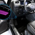
Accessing and interpreting OBDII data often involves using microcontrollers like the Arduino. One approach uses an Arduino UNO with a CAN bus shield. This setup allows direct data reading from the OBDII port’s pins, bypassing the serial port. For instance, GMLAN data can be accessed via pin 1 of the OBDII connector. Utilizing the onboard headers enables reading both high and low-speed CAN bus data.
The provided code example demonstrates how to interface an Arduino with a car’s CAN bus system. This code utilizes the CAN library for Arduino, enabling the sending and receiving of CAN packets. It includes functionality for simulating CAN packets for testing purposes and parsing received data. Importantly, the code defines different CAN speeds (LOW, MID, HIGH) catering to varying vehicle communication protocols.
Filtering OBDII PIDs for Dynamic Display
A common challenge when working with OBDII data is filtering the output to display only changed PIDs. This is crucial for creating dynamic displays that update only when a specific parameter changes, such as RPM (Revolutions Per Minute). This approach avoids overwhelming the user with a constant stream of unchanged data. Achieving this typically involves storing the previous state of each PID and comparing it to the current value. If a change is detected, the new value is then outputted to the serial monitor or a connected display.
One solution is to implement a data filtering mechanism within the Arduino code. This involves storing the last known value of each PID in an array or data structure. When a new CAN packet is received, the code compares the current PID values with their corresponding stored values. If a difference is found, the updated PID and its new value are sent to the serial monitor.
Further processing can be done using a Python script to format and display the filtered data on a custom dashboard or interface. This allows for a customized and efficient representation of real-time vehicle information. This approach provides a robust solution for building a dynamic and informative carputer or infotainment system. The focus on changed PIDs ensures efficient data utilization and enhances user experience.