In the realm of modern vehicle diagnostics, the EOBD/OBD-II system plays a crucial role in identifying potential issues. As an automotive repair expert at autelfrance.com, I frequently encounter various trouble codes, and one that often raises questions is U0101, indicating “Lost Communication with Transmission Control Module (TCM)”. This article delves into the intricacies of this diagnostic trouble code, providing a comprehensive guide for both DIY enthusiasts and professional technicians in the English-speaking automotive repair market.
Understanding the U0101 Code and its Significance
The U0101 code is a generic diagnostic trouble code, meaning it can appear across a wide range of vehicle makes and models. Essentially, it signals a communication breakdown between the Transmission Control Module (TCM) and other control modules within your vehicle’s network. To grasp the severity, it’s essential to understand the communication network itself.
Modern vehicles rely on a sophisticated network known as the Controller Area Network (CAN) bus. This network allows various electronic control units (ECUs), including the TCM, Engine Control Module (ECM), Anti-lock Braking System (ABS) module, and others, to exchange data seamlessly. Think of the CAN bus as the central nervous system of your car, facilitating vital communication for optimal vehicle operation. When the U0101 code appears, it means this communication pathway to the TCM has been disrupted.
Alt: Locating the OBD-II port in a vehicle interior, a crucial step for diagnosing EOBD/OBDII U0101 and other trouble codes.
Recognizing the Symptoms of a U0101 Fault
When communication with the TCM is lost, your vehicle’s performance is significantly impacted. Be alert for these common symptoms associated with the U0101 error code:
- Malfunction Indicator Lamp (MIL) Illumination: The check engine light or service engine soon light on your dashboard will likely illuminate, signaling a problem within the system.
- Transmission Shifting Issues: One of the most noticeable symptoms is erratic or absent gear shifting. The transmission might fail to shift gears, leading to poor acceleration and drivability.
- Stuck in Limp Mode: In many cases, the vehicle might enter “limp mode” or “fail-safe mode”. This typically means the transmission is locked in a single gear, often second or third, to prevent further damage and allow you to drive the vehicle to a repair shop at a reduced speed.
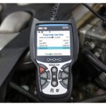
- Scan Tool Communication Failure: When diagnosing with an OBD-II scan tool, you might find that the tool cannot communicate with the TCM. This lack of communication reinforces the “lost communication” nature of the U0101 code.
- Other Module Communication Errors: Depending on the vehicle, other modules might also throw communication-related codes, indicating a broader network issue rather than just TCM isolation.
Pinpointing the Root Causes of U0101
Several factors can lead to a U0101 code. Understanding these potential causes is the first step towards effective diagnosis and repair:
- CAN Bus Circuit Malfunctions: The most frequent culprits are issues within the CAN bus wiring itself. This includes:
- Open Circuit in CAN Bus + or CAN Bus -: A break or disconnection in either of the CAN bus wires (+ or -) disrupts signal transmission.
- Short Circuit to Power in CAN Bus Circuit: If a CAN bus wire accidentally shorts to a power source, it can interfere with communication.
- Short Circuit to Ground in CAN Bus Circuit: Similarly, a short to ground in a CAN bus wire can also cause communication failure.
- Power and Ground Supply Issues to the TCM: The TCM, like any electronic module, requires stable power and ground connections to operate.
- Blown Fuses: A blown fuse in the TCM’s power supply circuit is a common and easily overlooked cause.
- Faulty Ground Connections: Corroded or loose ground connections can prevent the TCM from receiving adequate grounding, leading to malfunction and communication loss.
- Internal TCM Failure (Rare): While less common, the TCM itself can fail internally. However, this is usually diagnosed after ruling out all external wiring and power supply issues.
- Wiring Harness and Connector Problems: Physical damage to the wiring harness or connectors associated with the CAN bus or TCM can also lead to communication loss. Look for:
- Damaged Wires: Scraped, chafed, or broken wires.
- Corroded or Loose Connectors: Terminals within the connectors might be corroded, bent, or loose, hindering proper electrical contact.
Alt: A Transmission Control Module (TCM), the core component affected when diagnosing a U0101 error code related to lost communication.
Step-by-Step Diagnostic Procedure for U0101
Diagnosing a U0101 code requires a systematic approach. Here’s a step-by-step procedure to effectively troubleshoot this communication fault:
-
Preliminary Checks and TSB Review:
- Scan for All DTCs: Begin by scanning the vehicle’s computer system for all Diagnostic Trouble Codes (DTCs). Note down all present codes, as other codes, especially communication or power-related codes, can provide valuable clues.
- Check for Technical Service Bulletins (TSBs): Consult manufacturer-specific TSBs. There might be known issues or recalls related to U0101 or TCM communication problems for your vehicle model. Addressing a known issue can save significant diagnostic time.
-
Focus on Communication:
- Attempt TCM Communication with Scan Tool: Try to directly communicate with the TCM using your scan tool. If you cannot establish communication specifically with the TCM while other modules respond, it strongly suggests a TCM-specific communication problem.
- Prioritize Other Communication DTCs: If other communication-related codes are present (e.g., U0001, U0100), address these first. A fundamental CAN bus issue might be masking the U0101 problem.
-
Power and Ground Inspection:
- Fuse Check: Locate the fuses that supply power to the TCM (refer to the vehicle’s wiring diagram). Test each fuse for continuity using a multimeter. Replace any blown fuses.
- Ground Circuit Verification: Identify the TCM ground points (again, consult wiring diagrams). Visually inspect ground connections for corrosion or looseness. Clean and tighten ground connections as needed. Use a multimeter to verify ground continuity between the TCM ground terminal and the vehicle chassis ground.
-
CAN Bus Circuit Testing:
- Visual Inspection of Wiring and Connectors: Carefully examine the CAN bus wiring and connectors, especially those near the TCM and along the CAN bus network path. Look for any signs of damage, such as chafing, cuts, or melted insulation. Inspect connector terminals for corrosion, bending, or damage.
- Voltage Checks on CAN Bus: With the key in the “ON” position and engine OFF, use a digital voltmeter (DVM) to measure voltage on the CAN bus circuits at the TCM connector.
- CAN C+ (or HSCAN +): Expect to see approximately 2.5-3.5 volts, fluctuating slightly.
- CAN C- (or HSCAN -): Expect to see approximately 1.5-2.5 volts, fluctuating slightly.
- Voltage deviations outside these ranges can indicate shorts or opens in the CAN bus circuit.
- Continuity Testing of CAN Bus Wires: Disconnect the battery and TCM connector. Use a DVM in Ohms mode to check for continuity and shorts in the CAN bus wires:
- Continuity between CAN C+ terminals: Verify continuity between CAN C+ terminals at different modules along the CAN bus.
- Continuity between CAN C- terminals: Verify continuity between CAN C- terminals at different modules.
- Short to Ground/Power: Check for shorts to ground and power by testing for resistance between each CAN bus wire and ground, and each CAN bus wire and a 12V power source. Ideally, you should see very high resistance (open circuit). Low resistance indicates a short.
-
TCM Connector Pin Inspection and Cleaning:
- Disconnect TCM Connector: Disconnect the TCM connector.
- Terminal Inspection: Carefully inspect the terminals (pins) within the TCM connector and the mating connector on the wiring harness. Look for bent, broken, corroded, or pushed-out pins.
- Connector Cleaning: If corrosion is present, use electrical contact cleaner and a small plastic brush to gently clean the terminals. Allow to dry completely. Apply dielectric grease to the terminals before reconnecting to improve contact and prevent future corrosion.
-
Module Replacement (Last Resort):
- Suspect TCM Failure Only After Thorough Checks: Only consider TCM replacement after meticulously ruling out all external wiring, power, ground, and CAN bus circuit issues.
- Programming/Calibration Required: Be aware that replacing the TCM often requires programming or calibration to the specific vehicle using specialized diagnostic equipment. This step is crucial for proper TCM function and vehicle operation.
Resolving the U0101 Code
Once the diagnostic process identifies the root cause, repair involves addressing the specific issue:
- Repairing Wiring Issues: If you find open circuits, shorts, or damaged wires in the CAN bus or TCM power/ground circuits, repair or replace the affected wiring sections. Ensure proper splicing and insulation for reliable repairs.
- Replacing Fuses: Replace any blown fuses with the correct amperage rating. Investigate why the fuse blew in the first place to prevent recurrence.
- Cleaning and Tightening Connections: Thoroughly clean and tighten any corroded or loose ground or connector terminals. Use dielectric grease on connector terminals to prevent future corrosion.
- TCM Replacement and Programming: If TCM failure is confirmed (after exhausting all other possibilities), replace the TCM with a new or known-good module. Ensure the replacement TCM is correctly programmed and calibrated to the vehicle’s specifications.
Seeking Professional Assistance
Diagnosing and repairing communication faults like U0101 can be complex, requiring specialized tools and knowledge of vehicle electrical systems. If you are uncomfortable performing these diagnostic steps or lack the necessary equipment, it’s advisable to seek assistance from a qualified automotive technician. Professionals have access to advanced diagnostic tools, wiring diagrams, and the expertise to accurately pinpoint and resolve these intricate issues, ensuring a reliable and lasting repair.
By understanding the U0101 code, its symptoms, causes, and diagnostic procedures, you can effectively approach this challenging automotive problem and restore your vehicle’s communication network, getting you back on the road safely.