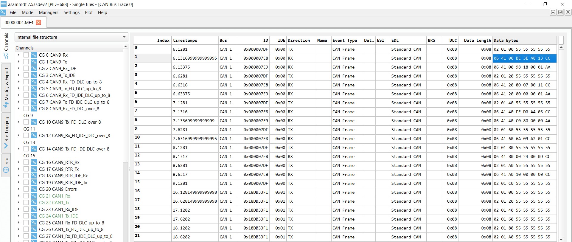
The OBDII connector, a critical component of your vehicle’s onboard diagnostics system, allows access to a wealth of data about your car’s performance. This guide provides a comprehensive overview of the OBDII connector, including its functionality, testing procedures, and common uses.
What is an OBDII Connector?
The OBDII (On-Board Diagnostics II) connector is a standardized 16-pin port located near the steering wheel of most vehicles manufactured after 1996. It serves as the interface between your car’s internal computer and external diagnostic tools, enabling mechanics and car enthusiasts to retrieve diagnostic trouble codes (DTCs), monitor real-time data, and perform various tests.
Why Perform an OBDII Connector Test?
An Obdii Connector Test is crucial for several reasons:
- Diagnose Vehicle Issues: Retrieve DTCs to pinpoint the source of malfunctions, such as check engine lights.
- Monitor Vehicle Performance: Access real-time data like speed, RPM, fuel levels, and engine temperature.
- Assess Emissions Compliance: Verify if the vehicle meets emissions standards.
- Preventative Maintenance: Identify potential problems before they escalate into major repairs.
- Customize Vehicle Settings: Access and modify certain vehicle parameters (depending on the vehicle and tool).
How to Perform an OBDII Connector Test
An OBDII connector test typically involves using a scan tool or code reader:
- Locate the OBDII Connector: Usually found under the dashboard near the steering wheel.
- Connect the Scan Tool: Plug the scan tool into the OBDII port.
- Turn on the Ignition: Turn the ignition key to the “on” position without starting the engine.
- Read Codes/Data: The scan tool will communicate with the vehicle’s computer and display DTCs or real-time data.
 OBDII scan tool
Understanding OBDII Communication Protocols
While the connector itself is standardized, various communication protocols govern how data is transmitted. The most common protocol is CAN (Controller Area Network), defined by ISO 15765-4. Other older protocols include ISO 9141-2, ISO 14230-4 (KWP2000), SAE J1850 VPW, and SAE J1850 PWM.
OBDII Parameter IDs (PIDs)
OBDII uses Parameter IDs (PIDs) to request specific data from the vehicle’s computer. Each PID corresponds to a particular parameter, such as engine speed or coolant temperature. Mode $01 is commonly used for real-time data, while other modes address specific functions like retrieving DTCs (Mode $03) or freeze frame data (Mode $02).
Beyond Basic OBDII Connector Tests
Advanced OBDII connector tests may involve:
- Data Logging: Recording data over time for analysis and performance monitoring using dedicated data loggers.
- Bi-directional Control: Certain scan tools allow for controlling vehicle components for testing purposes.
- Programming and Coding: Modifying vehicle settings and functionalities.
Conclusion
The OBDII connector test is an essential tool for diagnosing, monitoring, and maintaining modern vehicles. Understanding its functionality and utilizing appropriate diagnostic tools allows for efficient troubleshooting and informed decision-making regarding vehicle maintenance and repair. Whether you’re a professional mechanic or a car enthusiast, mastering the OBDII connector test empowers you to unlock valuable insights into your vehicle’s performance.
